We often receive questions from customers about why their antennas don't work as expected. The signal drops. The connection fails. After 17 years in this industry, I've seen how small details make huge differences in antenna performance.
Antenna performance depends on multiple interconnected factors including frequency match, physical design, installation environment, polarization alignment, and connector quality. Each element directly impacts signal strength, coverage range, and connection stability in real-world applications.

Understanding these factors helps you choose the right antenna and install it correctly. Let me walk you through each critical element that shapes antenna effectiveness.
What Determines Antenna Performance?
Many customers assume all antennas work the same way. They don't. Performance starts with the fundamental design parameters that define how an antenna interacts with radio waves.
The main determinants of antenna performance are frequency range, gain, radiation pattern, impedance matching, and polarization type. These parameters must align with your specific application requirements to achieve optimal signal transmission and reception.

Understanding the Core Performance Metrics
Frequency range defines which radio waves the antenna can handle. A 2.4GHz WiFi antenna won't work for 5G applications. We manufacture antennas covering different bands - 3G/4G/LTE, 5G, LoRa, WiFi, and GPS/GNSS. Each requires precise tuning.
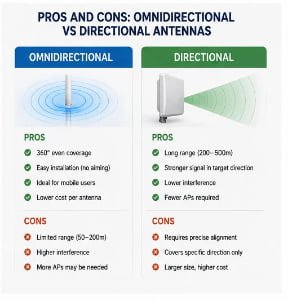
Gain measures how well an antenna focuses energy in specific directions. Higher gain means stronger signal in the target direction but narrower coverage. Lower gain provides wider coverage but less focused power. The trade-off matters for your application.
| Parameter | Impact on Performance | Typical Values |
|---|---|---|
| Frequency Range | Determines compatible devices and services | 700MHz-6GHz for cellular |
| Gain (dBi) | Affects signal strength and coverage pattern | 2-15dBi for omnidirectional |
| VSWR | Reflects impedance matching quality | <2.0 ideal, <1.5 excellent |
| Polarization | Must match transmitter for maximum efficiency | Vertical, horizontal, circular |
| Radiation Pattern | Defines coverage shape and direction | 360° omnidirectional or directional |
Impedance matching ensures maximum power transfer between antenna and cable. Poor matching causes signal reflection, measured as VSWR (Voltage Standing Wave Ratio). We target VSWR below 2.0 for most designs. Lower values mean better efficiency.
The radiation pattern shows where the antenna sends and receives signals. Omnidirectional antennas cover 360° horizontally, perfect for mobile applications. Directional antennas focus on specific areas, ideal for point-to-point links.
Key Factors That Influence Antenna Efficiency
Efficiency determines how much input power converts to radiated signal. Losses reduce performance. We've tested hundreds of designs to minimize these losses.
Antenna efficiency depends on material quality, conductor resistance, dielectric losses, and manufacturing precision. High-quality materials and precise construction directly translate to better signal conversion and reduced power waste.

Material Selection and Construction Quality
The choice of materials creates the foundation for antenna efficiency. Copper conductors offer excellent electrical properties, but they must be properly treated. We use high-purity copper for our radiating elements because impurities increase resistance and cause signal loss.
Dielectric materials separate conductors and shape the electromagnetic field. Low-loss dielectrics like Teflon or air perform best, but cost more. Standard FR4 circuit boards work for many applications but introduce some loss at higher frequencies. For 5G antennas operating above 3GHz, we often use specialized low-loss substrates.
Surface finish matters more than many realize. Oxidation increases resistance over time. We apply protective coatings to maintain long-term performance. Our outdoor antennas use UV-resistant materials because sun exposure degrades standard plastics within months.
| Efficiency Factor | Common Issue | Our Solution |
|---|---|---|
| Conductor resistance | Poor material quality | High-purity copper elements |
| Dielectric loss | Wrong substrate choice | Frequency-matched materials |
| Surface oxidation | Unprotected metals | Protective coatings |
| Assembly gaps | Manual alignment errors | Precision tooling |
| Connector quality | Generic components | Certified RF connectors |
Manufacturing precision directly affects efficiency. A 1mm misalignment in a 5GHz antenna shifts the frequency response noticeably. We use automated assembly for critical dimensions and manual inspection for quality control. Each batch undergoes testing in our anechoic chamber to verify performance matches design specifications.
Connection points create potential loss points. Every joint between antenna element and cable introduces some resistance. We minimize connections and use high-quality RF connectors. Cheap connectors lose more signal than the antenna itself in some cases.
What Impacts the Performance of an Antenna?
Installation environment changes everything. An antenna performing perfectly in our lab fails in certain real-world conditions. The surrounding environment interacts with radio waves in complex ways.
Environmental factors including ground plane, nearby metal objects, wall materials, mounting height, and weather conditions significantly impact antenna performance by altering radiation patterns, introducing reflections, and causing signal absorption.

The Ground Plane Effect
Ground plane size and quality dramatically affect antenna behavior, especially for monopole designs. A quarter-wave monopole antenna needs a conductive ground plane to function as designed. Too small, and the impedance shifts. The radiation pattern distorts.
We recently helped a customer troubleshoot poor performance in their industrial IoT devices. The antennas were mounted on small plastic enclosures. The lack of adequate ground plane caused high VSWR and reduced efficiency. We switched them to our nut-mount antennas with built-in ground planes. Performance improved immediately.
Metal objects near antennas cause problems through reflection and absorption. A metal cabinet reflects signals, creating dead zones. We learned this lesson years ago when customers complained about our suction cup antennas failing inside metal enclosures. The cabinet material caused severe signal reflection and distortion.
| Environmental Element | Impact | Mitigation Strategy |
|---|---|---|
| Metal enclosures | Signal reflection and shielding | Use nut-mount antennas with external mounting |
| Building materials | Signal absorption (concrete, metal) | Install antennas outside or use higher gain |
| Mounting height | Coverage area and line-of-sight | Position at optimal height for application |
| Weather (rain, snow) | Absorption at higher frequencies | Use weatherproof radomes |
| Ground plane size | Impedance and pattern distortion | Ensure adequate conductive surface |
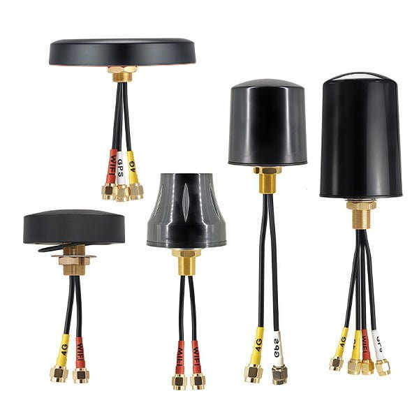
That's why we developed our nut-mount antenna series specifically for cabinet installations. The threaded mounting allows installation through the enclosure wall, placing the radiating element outside where it can operate properly. The nut provides secure fixing, excellent sealing, and vibration resistance.
Building materials matter significantly. Concrete walls contain metal reinforcement that blocks signals. Glass with metal coatings acts as a shield. Wood and standard glass allow signals through with minimal loss. When planning installations, we always ask customers about their environment. An antenna working perfectly in an open field might fail inside a concrete building.
Weather affects performance, particularly at higher frequencies. Rain absorbs millimeter-wave signals noticeably. Snow accumulation on outdoor antennas detunes the frequency response. Our fiberglass antennas use weather-resistant radomes that maintain performance in harsh conditions. We've supplied antennas operating reliably in Middle Eastern heat and European winters.
Main Elements Affecting Antenna Signal Quality
Signal quality determines how reliably data transmits. Poor signal quality causes dropped connections, reduced data rates, and communication errors. Multiple elements combine to determine the final signal quality.
Signal quality depends on signal-to-noise ratio, multipath interference, polarization matching, frequency accuracy, and interference from other sources. Each element must be optimized to achieve clean, reliable communication.

Multipath and Interference Issues
Multipath occurs when signals reach the receiver through multiple paths after reflecting off surfaces. The signals arrive at different times and can interfere constructively or destructively. In urban environments, buildings create complex multipath conditions. The received signal varies rapidly as you move even small distances.
I remember testing antennas downtown in a city surrounded by tall buildings. The signal strength fluctuated wildly over just a few meters of movement. This multipath fading challenges mobile applications. Our omnidirectional antennas with circular radiation patterns handle multipath better than directional designs in these situations.
Interference from other devices operating on nearby frequencies degrades signal quality directly. WiFi operates in crowded 2.4GHz and 5.8GHz bands shared with many devices. Bluetooth, microwave ovens, and wireless cameras all compete for the same spectrum. Good antenna design can't eliminate interference, but proper frequency selection helps.
| Signal Quality Factor | Problem | Solution |
|---|---|---|
| Multipath fading | Signal cancellation from reflections | Use diversity antennas or circular polarization |
| Co-channel interference | Multiple devices on same frequency | Choose less crowded channels |
| Adjacent channel interference | Nearby frequency signals bleeding over | Use antennas with better selectivity |
| Polarization mismatch | Wrong antenna orientation | Match transmitter polarization |
| Frequency drift | Temperature or aging effects | Use temperature-stable designs |
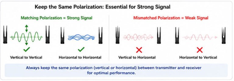
Polarization matching critically affects received signal strength. Radio waves have polarization - the orientation of the electric field. Vertical polarization aligns the electric field vertically. Horizontal polarization aligns it horizontally. The receiving antenna must match the transmitter's polarization.
This explains why we always tell customers to install omnidirectional antennas vertically. Base stations, mobile phones, and routers typically transmit with vertical polarization. Installing an antenna horizontally creates polarization mismatch. The signal loss can reach 20dB or more - reducing signal strength to just 1% of optimal.
Our dual-band omnidirectional antennas support both 2.4GHz and 5.8GHz, providing flexibility for different applications. The 2.4GHz band offers better penetration through walls and longer range. The 5.8GHz band provides higher bandwidth and lower latency. Many customers need both bands for complete coverage.
Understanding the Factors Behind Antenna Performance
Theoretical antenna design meets practical reality. We calculate expected performance using electromagnetic simulation software. Then we build prototypes and test them. The results often surprise us. Understanding why helps improve designs.
Real-world antenna performance results from complex interactions between electrical design, mechanical construction, material properties, and installation variables that often differ from theoretical predictions.

The Gap Between Theory and Practice
Simulation software assumes perfect materials and precise dimensions. Reality involves manufacturing tolerances, material variations, and assembly limitations. A design calling for a 50mm element might measure 50.2mm in production due to tooling limits. That small difference shifts the resonant frequency.
We've developed a database of correction factors over the years. When designing a new antenna, we apply these corrections to compensate for known manufacturing effects. The prototype then measures much closer to target specifications on the first iteration. This saves development time and reduces customer delays.
Temperature changes affect antenna performance through material expansion and electrical property shifts. Copper conductors expand when heated, slightly changing dimensions. Dielectric constants vary with temperature. An antenna tuned perfectly at room temperature might drift at extreme temperatures.
| Performance Gap | Cause | Engineering Approach |
|---|---|---|
| Frequency shift | Manufacturing tolerances | Apply correction factors from historical data |
| Gain reduction | Assembly variations | Use fixtures for consistent positioning |
| Pattern distortion | Mechanical flexing | Design structural supports |
| Temperature drift | Material property changes | Select stable materials and test across temperature range |
| Aging effects | Oxidation and material degradation | Use protective coatings and weatherproofing |
For outdoor antennas operating from -40°C to +85°C, we use materials with low temperature coefficients. We also test samples across the full temperature range to verify stable performance. Some customers in the Middle East need antennas surviving 70°C+ ambient temperatures. Standard designs fail in those conditions.
Mechanical stability matters more than electrical engineers often appreciate. An antenna element that flexes or vibrates changes its electrical characteristics dynamically. Vehicle-mounted antennas experience significant vibration. We use reinforced designs with proper mounting hardware to maintain stability.
The cable connecting the antenna to equipment forms part of the antenna system. Cable loss directly reduces effective antenna performance. A low-loss cable matters as much as the antenna itself. We offer complete cable assemblies using quality coaxial cable matched to the application requirements.
Critical Factors That Shape Antenna Effectiveness
Effectiveness measures how well an antenna accomplishes its intended purpose in the target application. A high-performance antenna becomes ineffective if mismatched to the application requirements.
Antenna effectiveness depends on matching the antenna characteristics to specific application requirements including frequency coverage, physical size constraints, environmental conditions, mounting options, and budget limitations.

Application-Specific Requirements
IoT devices need compact, efficient antennas operating on licensed or unlicensed bands. LoRa applications use sub-GHz frequencies for maximum range with minimal power. The antennas must fit inside small device enclosures while maintaining adequate performance. Size constraints force design compromises.
We recently developed a compact LoRa antenna for a customer's tracking device. The enclosure limited antenna space to 30mm x 10mm x 5mm. Standard quarter-wave designs wouldn't fit. We used a meandered element and careful impedance matching to achieve usable performance in the restricted space. Efficiency suffered compared to a full-size design, but the application prioritized size over maximum performance.
Vehicle-mounted antennas face unique challenges. They experience mechanical stress from vibration and wind forces. They must survive car washes and extreme weather. The mounting surface is metal, providing good ground plane but limiting placement options. Our vehicle antennas use robust mechanical designs with stainless steel hardware and weatherproof seals.
| Application | Key Requirements | Recommended Design |
|---|---|---|
| IoT sensors | Compact, low power, long range | Sub-GHz antenna with high efficiency |
| WiFi routers | Dual-band, omnidirectional, indoor | Vertical dipole or monopole |
| Vehicle tracking | Robust, weatherproof, good ground plane | Low-profile patch or stubby monopole |
| Base stations | High gain, directional, outdoor | Sector panel or Yagi array |
| Marine equipment | Extreme weather resistance, salt fog rated | Fiberglass whip with sealed base |
Router applications typically need dual-band coverage (2.4GHz and 5.8GHz) with omnidirectional patterns. Users expect consistent performance regardless of device location relative to the router. Our dual-band omnidirectional antennas provide 360° coverage in the horizontal plane with vertical polarization matching mobile devices.
Base station applications require directional antennas with higher gain to cover specific sectors. A 120° beamwidth serves one sector of a three-sector cell site. We manufacture sector panel antennas with 15-18dBi gain for these applications. The directional pattern reduces interference between sectors and increases range in the coverage area.
Marine and outdoor applications demand extreme weatherproofing. Salt fog accelerates corrosion dramatically. Standard antennas fail within months in marine environments. Our fiberglass antennas use UV-resistant radomes, sealed bases, and stainless steel hardware to survive years of harsh conditions. Customers operating in coastal areas or on ships require this level of protection.
How Different Factors Influence Antenna Performance
The factors affecting antenna performance interact in complex ways. Changing one parameter affects others. Understanding these relationships helps optimize overall system performance.
Multiple performance factors interact through electromagnetic coupling, mechanical dependencies, and thermal effects, requiring balanced design approaches that consider trade-offs between competing requirements.

Design Trade-offs and Interactions
Increasing antenna gain narrows the beamwidth. This fundamental relationship comes from basic antenna theory. You can't have both high gain and wide coverage with a single antenna element. Applications requiring both use antenna arrays or multiple antennas covering different sectors.
We often explain this trade-off to customers expecting unrealistic performance. They want an omnidirectional antenna with 20dBi gain. That violates the laws of physics. An omnidirectional antenna with typical 2-5dBi gain spreads energy in all horizontal directions. A 20dBi gain antenna focuses energy in a narrow beam, making it highly directional.
Bandwidth and antenna size trade off inversely in most designs. Smaller antennas have narrower bandwidth. The physical size relative to wavelength determines how much bandwidth the antenna can cover efficiently. This limits miniaturization for broadband applications.
| Interaction | Relationship | Design Implication |
|---|---|---|
| Gain vs. beamwidth | Inverse | Higher gain = narrower coverage |
| Size vs. bandwidth | Inverse | Smaller antenna = narrower bandwidth |
| Efficiency vs. cost | Direct | Better materials cost more |
| Complexity vs. reliability | Inverse | Simpler designs more reliable |
| Performance vs. environmental ruggedness | Often inverse |