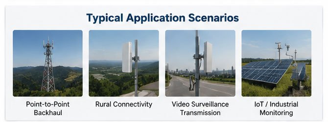
Choosing the right high gain communication antenna can make or break your wireless system performance. I've seen countless projects struggle simply because buyers focused on gain numbers without understanding how directivity, coverage patterns, and real-world installation factors actually work together. Your network deserves better than guesswork.
A high gain communication antenna concentrates radio frequency energy in specific directions to extend transmission range and improve signal quality. Higher gain (measured in dBi) means longer distance but narrower coverage angle, making proper selection critical for balancing your coverage area needs against transmission distance requirements based on your specific deployment scenario.
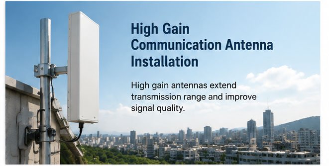
Understanding what gain actually means in practical terms will save you from expensive mistakes. Throughout this guide, I'll walk you through every critical decision point, from technical specifications to real-world performance factors that antenna datasheets often overlook.
Ultimate Guide to Choosing High Gain Communication Antennas?
When I first started working with communication systems over 17 years ago, I made the beginner's mistake of thinking "more gain equals better performance." That misconception cost our client significant coverage gaps.
Choosing a high gain communication antenna requires matching gain specifications to your coverage pattern needs, considering frequency compatibility, understanding VSWR performance, evaluating mechanical durability for your installation environment, and verifying connector compatibility with your equipment.
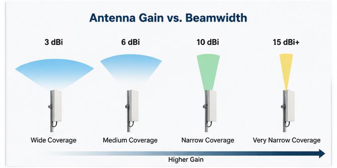
The fundamental principle works like this: antenna gain doesn't create power—it focuses existing power. Think of it like a flashlight compared to a floodlight. The flashlight (high gain antenna) throws light much farther but illuminates a smaller area. The floodlight (lower gain antenna) covers more area but with less distance.
Understanding Gain Measurements
Gain specifications appear in either dBi (decibels relative to isotropic) or dBd (decibels relative to dipole). Most manufacturers use dBi because it produces higher numbers—there's a 2.15 dB difference between them. A 5 dBd antenna equals approximately 7.15 dBi. Always verify which measurement you're comparing.
For practical applications:
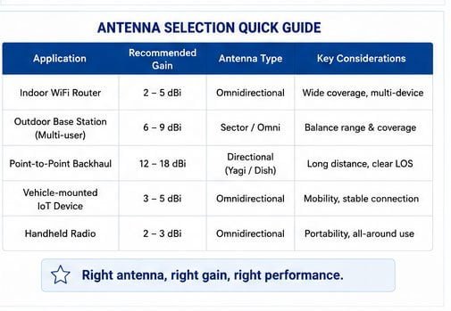
- 2-5 dBi: Wide coverage, short to medium range (WiFi routers, small office spaces)
- 6-9 dBi: Balanced coverage and distance (medium-sized facilities, point-to-multipoint systems)
- 10-15 dBi: Narrower beam, longer range (building-to-building links, directional coverage)
- 16+ dBi: Very narrow beam, maximum distance (point-to-point links, long-range applications)
The Coverage Pattern Trade-off
Here's the critical relationship many buyers miss: doubling the gain roughly halves the beamwidth. This inverse relationship means every gain increase narrows your coverage pattern. I've worked with customers who installed 15 dBi antennas expecting both long range AND wide coverage—they got neither effectively.
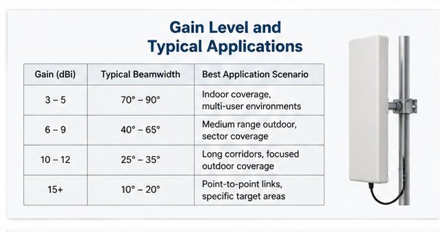
| Gain Level | Typical Beamwidth | Best Application Scenario |
|---|---|---|
| 3-5 dBi | 70-90° | Indoor coverage, multi-user environments |
| 6-9 dBi | 40-65° | Medium range outdoor, sector coverage |
| 10-12 dBi | 25-35° | Long corridors, focused outdoor coverage |
| 15+ dBi | 10-20° | Point-to-point links, specific target areas |
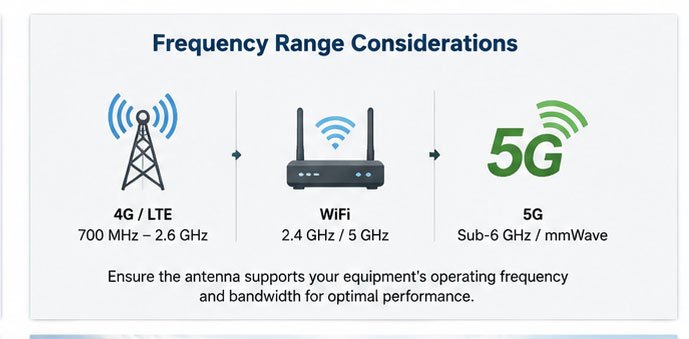
Frequency Range Considerations
Communication antennas are frequency-specific devices. A 4G LTE antenna won't work properly for WiFi, and a GPS antenna won't receive 5G signals. When selecting your high gain antenna, verify:
- Operating frequency matches your equipment (check the exact bands, not just technology names)
- Bandwidth covers all channels you'll use (some "5G antennas" only cover sub-6GHz, not mmWave)
- Gain remains consistent across the full frequency range (some antennas show peak gain at one frequency but drop significantly at band edges)
I recently helped a customer who bought "5G antennas" that only supported n77/n78 bands (3.3-3.8 GHz) when their equipment needed n41 band (2.5 GHz) coverage. The antenna physically connected but delivered poor performance because it operated outside its designed frequency range.
Polarization and MIMO Considerations
Modern communication systems increasingly use MIMO (Multiple Input Multiple Output) technology, requiring multiple antenna elements. When evaluating high gain MIMO antennas, consider:
- Polarization diversity (combining vertical and horizontal polarization improves multipath resistance)
- Spatial diversity (physical separation between antenna elements reduces correlation)
- Cross-polarization discrimination (XPD) values above 15 dB indicate good isolation
For 4x4 MIMO or higher configurations, antenna design becomes critical. Cramming four high gain elements into a small enclosure creates interference between elements, degrading the benefits of MIMO. Quality manufacturers use precise element spacing and isolation techniques—cheap alternatives often fail to deliver promised MIMO performance.
How to Buy the Best High Gain Communication Antenna?
My purchasing philosophy changed after seeing a client waste $50,000 on antennas that technically met specifications but failed in their actual installation environment.
Buying the best high gain communication antenna means starting with your coverage requirements, then working backward to specifications rather than starting with gain numbers. Define your coverage area, distance needs, mounting constraints, and environmental conditions before evaluating technical specifications or comparing suppliers.
The buying process works most effectively when you follow this sequence, which I've refined through hundreds of customer consultations.
Step 1: Define Your Actual Requirements
Before looking at any product catalogs, document these fundamental parameters:
Coverage requirements:
- Total area needing coverage (both horizontal and vertical dimensions)
- Acceptable dead zones or coverage gaps
- Minimum signal strength required throughout the coverage area
- Number of simultaneous users or devices
Distance and path considerations:
- Maximum link distance (for point-to-point) or coverage radius (for point-to-multipoint)
- Line-of-sight availability or obstacle types (buildings, trees, terrain)
- Indoor or outdoor installation
- Fixed or mobile endpoints
Environmental factors:
- Temperature range (-40°C to +70°C in some industrial applications)
- Wind loading (coastal or mountain installations need specific mechanical ratings)
- Moisture exposure (IP65 minimum for outdoor, IP67+ for marine environments)
- Lightning risk (proper grounding becomes critical)
I once worked with a customer planning a coastal monitoring system. They initially selected standard outdoor antennas rated IP65. After discussing their salt spray exposure and hurricane wind loads, we specified IP67-rated marine-grade antennas with reinforced mounting hardware. The initial cost increased by 30%, but they avoided replacement costs and system downtime.
Step 2: Calculate Required Gain
Rather than guessing at gain requirements, use the link budget formula to calculate what you actually need:
Received Power (dBm) = Transmit Power (dBm) + Tx Antenna Gain (dBi) - Path Loss (dB) - Other Losses (dB) + Rx Antenna Gain (dBi)
For example, a 2 km point-to-point link at 2.4 GHz with 100 mW (20 dBm) transmit power:
- Path Loss (free space): ~107 dB
- Cable losses (10m of cable): ~3 dB
- Connector losses: ~0.5 dB
- Required receive sensitivity: -85 dBm (typical for decent data rates)
Working backward: -85 = 20 + Tx Gain - 107 - 3.5 + Rx Gain
If using identical antennas: 2 × Gain = -85 - 20 + 107 + 3.5 = 5.5 dBi per antenna (minimum)
For practical deployment with margin for weather and interference, you'd specify 9-12 dBi antennas for this application.
Step 3: Evaluate Beyond the Datasheet
Technical datasheets tell part of the story. Smart buyers verify these additional factors:
Manufacturer reputation and track record:
- Years in business and production volume
- Quality certifications (ISO9001 minimum)
- Compliance testing (CE, FCC, RoHS as applicable)
- Customer references for similar applications
Physical construction quality:
- Radome material (UV-stable ASA or fiberglass, not cheap ABS plastic)
- Mounting hardware robustness (stainless steel, not zinc-plated mild steel)
- Cable entry sealing method (industrial connectors or proper cable glands)
- Internal element protection (potted electronics for harsh environments)
Support and warranty terms:
- Warranty period and what it covers
- Technical support availability
- Replacement policy and lead times
- Testing documentation and compliance certificates
Step 4: Consider Total Cost of Ownership
The purchase price represents only one component of total antenna costs:
| Cost Component | Typical Percentage | Consideration Factors |
|---|---|---|
| Initial purchase | 30-40% | Unit price, shipping, import duties |
| Installation | 20-30% | Labor, mounting hardware, cable runs, alignment time |
| Cabling and accessories | 15-20% | RF cables, connectors, lightning protection, grounding |
| Maintenance | 10-15% | Periodic inspection, cleaning, realignment, weather damage repair |
| Replacement | 10-15% | Failure rate, warranty coverage, spare parts availability |
A $200 antenna requiring $500 in custom mounting fabrication and frequent realignment may cost more over three years than a $400 antenna with standardized mounting and stable performance.
Step 5: Validate Compatibility and Integration
Before committing to purchase, confirm these integration points:
- Connector type matches your equipment or cables (N-type, SMA, TNC—gender and threading)
- Cable length won't exceed loss budget (longer runs need lower-loss cable or inline amplification)
- Mounting method works with your structure (pole mount, wall bracket, magnetic base, etc.)
- Physical size fits installation space (higher gain often means larger antenna dimensions)
- Power handling capacity exceeds your transmitter output (important for high-power applications)
I've seen projects delayed weeks because someone ordered N-type female antennas when their equipment had N-type female connectors—both were female, requiring additional adapters that introduced loss and weather sealing challenges.
High Gain Communication Antenna Selection Guide?
Selection becomes straightforward once you understand which antenna characteristics matter most for different application types.
Selecting the right high gain communication antenna depends on your specific use case: base station antennas prioritize vertical beamwidth control and side lobe suppression; point-to-point links need maximum gain with tight beamwidth; mobile applications require omnidirectional patterns even if it means accepting lower gain; and indoor systems balance gain against aesthetic and spatial constraints.
Let me break down the selection criteria by major application categories since each has distinct priorities.
Base Station and Access Point Antennas
When deploying fixed infrastructure serving multiple users, your antenna selection centers on coverage pattern control rather than maximum gain. I've learned this through watching poorly planned deployments create co-channel interference and coverage holes.
Key selection criteria:
Horizontal beamwidth: Determines sector coverage
- 360° omnidirectional: Simple deployment, but creates overlap and interference in multi-AP environments
- 60-90° sector antennas: Allow frequency reuse in adjacent sectors, common in outdoor deployments
- 120° sector antennas: Balance between coverage and frequency reuse, popular for three-sector sites
Vertical beamwidth and downtilt: Controls coverage distance and interference
- Narrow vertical beamwidth (8-15°) pushes signal horizontally with minimal ground or sky radiation
- Electrical or mechanical downtilt angles signal toward ground level, reducing interference with distant sites
- Front-to-back ratio (F/B) above 20 dB prevents backside coverage causing interference behind antenna
Gain implications for base stations:
Higher gain in base station antennas typically narrows the vertical beamwidth while maintaining horizontal coverage. This pattern works well for:
- Flat terrain deployments (gain extends horizontal range without wasting energy skyward)
- Dense user environments (controlled vertical pattern reduces multi-floor interference in buildings)
- Reducing adjacent site interference (narrower vertical pattern means less spillover)
For urban environments with buildings of varying heights, moderate gain (10-14 dBi) with slightly wider vertical beamwidth often outperforms very high gain (16+ dBi) narrow-beam antennas because it maintains better coverage across different elevation angles.
Point-to-Point Link Antennas
When connecting two fixed points, selection priorities shift entirely toward maximum gain and tight beamwidth since you're targeting one specific location.
Optimization factors:
Maximum practical gain: Limited by physical size and frequency
- Parabolic dish antennas deliver the highest gain for their size (18-30 dBi common)
- Flat panel antennas offer easier mounting with slightly less gain (14-23 dBi typical)
- Yagi antennas provide moderate gain with lowest wind loading (12-17 dBi range)
Beamwidth precision: Narrower beams require more careful alignment
- 3 dB beamwidth indicates where signal drops to half power
- 10° beamwidth (common with 18 dBi gain) needs precision mounting hardware
- Alignment tolerance of ±1-2° requires skilled installation and stable mounting
Fresnel zone clearance: Higher gain means narrower Fresnel zones requiring less clearance
- First Fresnel zone must be at least 60% clear of obstacles
- Higher frequency and higher gain antennas have smaller Fresnel zones
- Trees growing into the path cause seasonal performance variation
I helped design a 5 km link between two buildings where the customer wanted 24 dBi dish antennas for "maximum performance." After site survey, we discovered significant tree growth in the path that moved with wind. We specified 18 dBi panel antennas with wider beamwidth—they tolerated minor alignment shifts from wind and vegetation movement better than ultra-narrow dish antennas would have.
Mobile and Vehicular Antennas
Applications on moving platforms create unique selection challenges because orientation constantly changes.
Critical mobile antenna characteristics:
Omnidirectional or wide-angle patterns: Maintain connection regardless of vehicle orientation
- True omnidirectional antennas (2-5 dBi) work everywhere but sacrifice range
- Dual-polarization designs improve multipath handling in urban environments
- Roof mounting provides better ground plane and all-around coverage than glass-mount options
Mechanical durability: Vibration, weather, and impact resistance exceed fixed installations
- Spring-loaded base absorbs impacts from low clearance (car washes, garage doors)
- Direct cable connection (no external connectors) eliminates moisture entry points
- Compact form factor reduces wind drag and vandalism risk
MIMO requirements for mobile data: Modern 4G/5G systems require multiple antenna elements
- Minimum 30 cm spacing between elements for 2x2 MIMO effectiveness
- Combined multi-band antennas pack multiple frequencies into one housing
- Shark fin designs balance aesthetics with electrical performance
For vehicle installations, I always recommend professional-grade antennas even though they cost 3-5x more than consumer versions. Consumer antennas use inferior cable and connectors that fail within months from vibration, while commercial-grade antennas often outlast the vehicle itself.
Indoor Coverage Antennas
Indoor deployments face unique propagation challenges from walls, metal structures, and electronic interference.
Indoor selection priorities:
Aesthetic considerations: Office and commercial spaces resist obtrusive installations
- Low-profile ceiling mount antennas blend into drop ceiling tiles
- Desktop omnidirectional antennas (3-5 dBi) suit small offices and conference rooms
- Panel antennas mounted on walls direct coverage into specific areas
Building penetration: Interior walls attenuate signals differently than free space
- Drywall: 3-5 dB loss per wall
- Concrete: 10-15 dB loss per wall
- Metal studs or rebar: 20+ dB loss with severe multipath
Lower gain antennas (3-7 dBi) often perform better indoors than high gain options because:
- Wider vertical beamwidth covers multiple floors in the same building
- Broader pattern creates useful reflections off walls and ceilings
- Reduced directionality simplifies installation and reduces dead zones
I've learned that indoor antenna deployment density matters more than individual antenna gain. Three strategically placed 5 dBi antennas almost always outperform one 15 dBi antenna for the same total space, because the multiple locations reduce dead zones created by the building structure.
Complete High Gain Communication Antenna Buyer's Guide?
Navigating the actual purchasing process requires attention to procurement details that go beyond pure technical specifications.
**A complete buying approach addresses supplier qualification, specification verification, testing requirements, delivery logistics, and installation planning as integrated steps rather