In our 17 years of manufacturing RF antennas, I've seen countless projects fail—not because of poor antenna design, but because customers overlooked the cable connecting the antenna to their device. That seemingly insignificant RF cable is actually the lifeline of your entire wireless system.
Coaxial cables are ideally suited for RF transmission because they use a shielded, symmetrical structure that confines electromagnetic fields within the cable, preventing signal leakage and external interference while maintaining consistent impedance across the signal path, which is critical for high-frequency performance.

Think of your antenna as the eyes and ears of your wireless device. But what good are sharp eyes if the optic nerve is damaged? That's exactly what happens when you use improper RF cabling. Let me walk you through why coaxial cables have become the industry standard for RF transmission.
Why Are Coaxial Cables Ideal for RF Signal Transmission?
I remember a customer from Germany who came to us frustrated. His IoT gateway worked perfectly in the lab but failed in the field. After testing, we discovered his custom cable had inconsistent impedance. This is where coaxial cables shine.
Coaxial cables are ideal for RF transmission because their concentric structure creates a closed electromagnetic field that isolates the signal from external noise while maintaining constant impedance, ensuring maximum power transfer and minimal reflection across the entire frequency range.

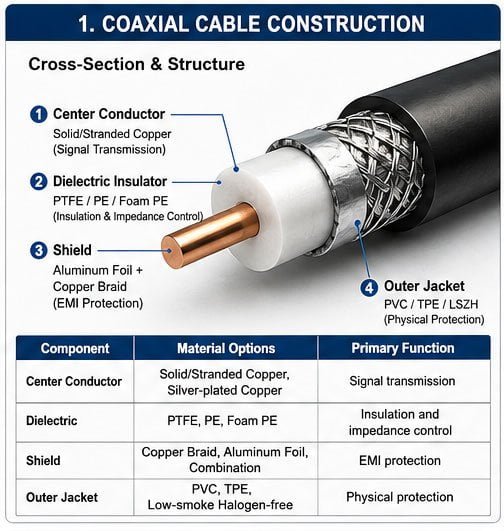
The secret lies in the geometry. When we manufacture RF cable assemblies, we pay extreme attention to three critical aspects:
First, the center conductor carries the signal. We typically use solid copper or stranded copper wire depending on flexibility requirements. Solid works better for fixed installations, while stranded handles repeated flexing better.
Second, the dielectric insulator surrounds the center conductor. This material—often PTFE, PE, or foam PE—determines the cable's velocity factor and capacitance. I've tested hundreds of samples, and the dielectric quality directly impacts signal speed and loss.
Third, the outer shield wraps around everything. This can be braided copper, aluminum foil, or both. The shield serves two purposes: it prevents your signal from radiating outward and blocks external interference from entering.
| Component | Material Options | Primary Function |
|---|---|---|
| Center Conductor | Solid/Stranded Copper, Silver-plated Copper | Signal transmission |
| Dielectric | PTFE, PE, Foam PE | Insulation and impedance control |
| Shield | Copper Braid, Aluminum Foil, Combination | EMI protection |
| Outer Jacket | PVC, TPE, Low-smoke Halogen-free | Physical protection |
What makes this structure brilliant for RF is the coaxial geometry itself. The center conductor and shield share the same axis—that's where "coaxial" comes from. This symmetry creates a balanced electromagnetic field trapped between the conductors. External signals can't penetrate easily, and your signal stays contained.
What Makes Coaxial Cable Effective for High-Frequency RF Applications?
Last month, we supplied cables for a 5G base station project in Southeast Asia. The customer needed cables that could handle frequencies up to 6 GHz with minimal loss. This is where understanding high-frequency behavior becomes critical.
Coaxial cables remain effective at high frequencies because their controlled geometry maintains consistent characteristic impedance and their shielding prevents radiation losses, while the skin effect is managed through proper conductor selection and the dielectric minimizes frequency-dependent attenuation.

At high frequencies, several physical phenomena become significant. I've measured this countless times in our lab, and the results always confirm the same patterns.
The skin effect pushes current to the outer surface of conductors. As frequency increases, current flows in a thinner layer. This increases resistance and causes loss. Quality coaxial cables address this through larger conductors or silver plating, which has better conductivity than copper.
Dielectric loss also increases with frequency. The insulating material between conductors absorbs some energy. We select low-loss dielectrics like PTFE for applications above 3 GHz. For standard applications, solid PE works fine up to 2.4 GHz.
Impedance consistency matters more at high frequencies. Any variation in the distance between center conductor and shield creates impedance bumps. These bumps reflect energy back toward the source, reducing efficiency. Our manufacturing process maintains tolerances within ±2 ohms for 50-ohm cables.
Here's what happens at different frequency ranges:
| Frequency Range | Primary Challenges | Cable Considerations |
|---|---|---|
| Below 1 GHz | Basic loss, interference | Standard RG cables work well |
| 1-3 GHz | Increased loss, impedance matching | Low-loss cables recommended |
| 3-6 GHz | Significant dielectric loss, skin effect | Premium dielectrics, larger conductors |
| Above 6 GHz | Severe attenuation, mode propagation | Specialized cables, semi-rigid options |
The coaxial structure prevents another high-frequency problem: radiation. An unshielded wire acts as an antenna at RF frequencies, radiating energy into space. The shield traps this energy inside, where it belongs. I've seen systems lose 3-6 dB of signal simply from using inadequate shielding.
How Does Coaxial Cable Support Reliable RF Communication?
We once worked with a fleet management company whose GPS tracking devices randomly lost connection. After visiting their installation, I found they'd routed antenna cables alongside power lines. The interference was destroying their signal quality.
Coaxial cables support reliable RF communication by providing electromagnetic isolation through multi-layer shielding, maintaining signal integrity through impedance control, and offering mechanical stability through proper jacket design, which together ensure consistent performance across environmental conditions and installation scenarios.

Reliability in RF communication depends on three factors: signal strength preservation, noise immunity, and physical durability. Coaxial cables address all three simultaneously.
Signal preservation starts with low insertion loss. Every meter of cable attenuates your signal. At 2.4 GHz, a standard RG58 cable loses about 1 dB per meter, while premium LMR400 loses only 0.22 dB per meter. Over a 5-meter run, that's 5 dB versus 1.1 dB—a massive difference in received signal strength.
Noise immunity comes from shielding effectiveness. We measure this in decibels. A cable with 90 dB shielding blocks 99.999% of external interference. Our double-shielded cables typically achieve 85-95 dB across the frequency range. This matters tremendously in industrial environments with motors, inverters, and switching power supplies.
Mechanical stability ensures electrical performance doesn't degrade. I've tested cables that failed after 100 bend cycles, and others that survived 10,000 cycles. The difference lies in conductor design, jacket material, and assembly quality.
Consider what happens during installation and operation:
| Reliability Factor | How Coaxial Design Addresses It | Measurement Standard |
|---|---|---|
| Insertion Loss | Conductor size, dielectric quality | dB per meter at specified frequency |
| Shielding Effectiveness | Braid coverage, foil layers | dB attenuation of external signals |
| VSWR | Impedance consistency | Ratio, ideally below 1.5:1 |
| Bend Durability | Stranded conductors, flexible jacket | Number of flex cycles |
| Temperature Stability | Jacket material selection | Operating range (-40°C to +85°C typical) |
Temperature affects cable performance. The dielectric expands and contracts, slightly changing impedance. Quality cables use materials with low temperature coefficients. Our cables maintain specifications from -40°C to +85°C, which covers most outdoor installations.
Why Is Coaxial Cable Commonly Used in RF Systems?
After 17 years in this industry, I can tell you the answer is simple: nothing else works as well for the price. I've evaluated twisted pair, waveguide, and even optical solutions. Each has its place, but coaxial cable offers the best compromise for most applications.
Coaxial cables dominate RF systems because they provide excellent electrical performance at reasonable cost, offer flexibility in installation compared to rigid waveguides, support a wide frequency range with standardized connectors, and maintain compatibility across decades of equipment development.

Let me break down why engineers like me specify coaxial cable for almost every project. The reasons go beyond just technical performance—they touch on practical realities of building wireless systems.
Cost effectiveness stands out immediately. A 5-meter LMR400 cable costs about $30-50, while equivalent waveguide costs $500-800. For a small cell tower with 20 antenna connections, that's $1,000 versus $16,000 just for cables. This matters especially for our customers deploying thousands of IoT devices.
Installation flexibility makes coaxial cable practical. I can route it through conduits, around corners, and along existing cable trays. Waveguide requires straight runs and special mounting. Fiber optic needs careful handling and fusion splicing. Coaxial cable tolerates rougher treatment and connects with simple crimp or solder.
The standardization ecosystem is enormous. When I specify N-type connectors on LMR400, any technician worldwide knows exactly what to do. Test equipment, adapters, and replacement parts are universally available. This reduces project risk and speeds up deployment.
Here's how coaxial cable compares to alternatives:
| Transmission Medium | Frequency Range | Installation Complexity | Relative Cost | Loss Characteristics |
|---|---|---|---|---|
| Coaxial Cable | DC to 40+ GHz | Low (flexible, standard connectors) | Baseline (1x) | Moderate, increases with frequency |
| Twisted Pair | DC to 1 GHz | Very Low | Very Low (0.3x) | High above 100 MHz |
| Waveguide | 1 to 300+ GHz | High (rigid, precise alignment) | Very High (10-20x) | Very low at design frequency |
| Fiber Optic | N/A (optical) | Moderate (requires conversion) | Moderate (2-3x) | Very low, but needs converters |
Compatibility across frequencies deserves emphasis. A single coaxial cable can carry GPS signals at 1.5 GHz, WiFi at 2.4 and 5.8 GHz, and LTE at multiple bands simultaneously. We design multi-band antennas that work across 698-6000 MHz, and coaxial cable supports this entire range without modification.
What Features Make Coaxial Cables Suitable for RF Transmission?
When I train new engineers on our team, I always start with cable anatomy. Understanding the features that enable RF transmission helps in selecting the right cable for each application.
Key features that make coaxial cables suitable for RF transmission include controlled characteristic impedance matching industry standards, low-loss dielectric materials, comprehensive electromagnetic shielding, balanced mechanical and electrical properties, and compatibility with standardized connector systems.

Let me walk through the critical features one by one, explaining why each matters based on what I've learned from thousands of installations.
Characteristic impedance standardization enables system design. Almost all RF systems use either 50-ohm or 75-ohm impedance. We manufacture cables to meet these standards within ±2 ohms. This matching minimizes reflections and maximizes power transfer. When impedance mismatches occur, you get standing waves that reduce efficiency.
Low-loss dielectric selection directly impacts signal preservation. I've tested cables with different dielectrics side by side. PTFE (Teflon) offers the lowest loss but costs more. Solid polyethylene works well for frequencies below 3 GHz. Foam polyethylene provides a middle ground with lower dielectric constant, which reduces loss while maintaining good mechanical properties.
Multi-layer shielding provides isolation. Our standard cables use aluminum foil plus copper braid. The foil blocks high-frequency interference, while the braid handles low-frequency noise and provides mechanical strength. For demanding applications, we add a second foil layer, achieving over 90 dB shielding effectiveness.
| Cable Feature | Technical Specification | Impact on RF Performance |
|---|---|---|
| Impedance | 50Ω ±2Ω (RF), 75Ω ±2Ω (Video) | Minimizes VSWR, maximizes power transfer |
| Dielectric Constant | 1.2 (foam) to 2.3 (solid PE) | Affects velocity factor and capacitance |
| Shield Coverage | 85% (single braid) to 100% (foil+braid) | Determines isolation level |
| Velocity Factor | 0.66 (solid) to 0.88 (foam/air) | Impacts signal propagation speed |
| Power Rating | Varies with cable size and frequency | Maximum transmit power capability |
Flexibility versus performance represents a key design tradeoff. Solid center conductors offer lower DC resistance but break under repeated flexing. Stranded conductors handle movement better but have slightly higher loss. For fixed installations like base stations, I recommend solid conductors. For mobile applications like vehicle antennas, stranded is essential.
Connector compatibility ensures reliable connections. We terminate our cables with SMA, N-type, TNC, or BNC connectors depending on application. Each connector type has frequency and power limitations. SMA works to 18 GHz but handles less power than N-type. Understanding these limits prevents field failures.
How Do Coaxial Cables Minimize Signal Loss in RF Transmission?
Signal loss frustrates every RF engineer. I've debugged systems where poor cables reduced range by 60%. Understanding loss mechanisms helps you choose the right cable and installation method.
Coaxial cables minimize RF signal loss through large conductor sizing that reduces resistive loss, high-quality dielectrics with low dissipation factors, proper impedance matching that eliminates reflection losses, and effective shielding that prevents radiation loss.

Loss in coaxial cables comes from four sources. I measure each one separately when qualifying new cable types for our product line.
Conductor loss happens because copper has resistance. Current flow generates heat, which steals energy from your signal. This loss increases with frequency due to skin effect. At 1 GHz, current flows in a layer only about 2 microns deep. Larger conductors have more surface area, spreading current over a bigger area and reducing resistance. This is why LMR400 outperforms RG58—it has much larger conductors.
Dielectric loss occurs when the insulator between conductors absorbs RF energy. Every material has a loss tangent or dissipation factor. Lower is better. PTFE has a dissipation factor of 0.0002, while PVC is around 0.02—100 times worse. For high-frequency applications above 3 GHz, I always recommend PTFE-based cables.
Radiation loss happens when the shield fails to contain electromagnetic fields. Poor shielding lets your signal leak out, weakening it before reaching the destination. This becomes severe near connectors if improperly installed. I've measured 2-3 dB additional loss from poorly crimped connectors that create shield gaps.
Reflection loss stems from impedance mismatches. When the cable impedance doesn't match the source or load, some energy reflects back instead of transmitting forward. This shows up as poor VSWR (Voltage Standing Wave Ratio). A VSWR of 2:1 means about 10% of your power reflects back—wasted.
Here's how different cables perform across frequency:
| Cable Type | Loss at 1 GHz | Loss at 2.4 GHz | Loss at 5.8 GHz | Typical Application |
|---|---|---|---|---|
| RG58 | 0.7 dB/m | 1.1 dB/m | 1.9 dB/m | Short runs, legacy systems |
| RG213 | 0.4 dB/m | 0.65 dB/m | 1.2 dB/m | General purpose |
| LMR240 | 0.4 dB/m | 0.6 dB/m | 1.0 dB/m | Compact installations |
| LMR400 | 0.14 dB/m | 0.22 dB/m | 0.38 dB/m | Professional installations |
| LMR600 | 0.09 dB/m | 0.15 dB/m | 0.25 dB/m | Long runs, high power |
For a typical 5-meter antenna cable run at