I remember when a client first asked me about nut antennas. He was frustrated with signal drops on his agricultural equipment. After switching to our nut-mounted design, his entire fleet stayed connected. That is when I realized how underrated this mounting style really is.
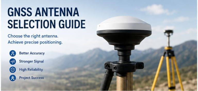
A nut antenna is a communication antenna designed with a threaded nut base for secure panel mounting. It provides stable signal transmission in mobile and outdoor environments. This design is widely used in vehicles, IoT devices, and industrial equipment where vibration resistance and reliable connectivity are critical.

Many people overlook the importance of how an antenna is mounted. But I have seen countless projects fail simply because the antenna could not stay firmly attached. The nut antenna solves this problem with a simple, proven mechanical design that works even in harsh conditions.
What Is the Structure of a Nut Antenna?
I often get asked what makes a nut antenna different from other types. The confusion is understandable. From the outside, it looks like any other antenna. But the real difference lies in how it attaches to your device or vehicle.
A nut antenna consists of a radiating element, a threaded metal base, and a mounting nut. The threaded base passes through a drilled hole in the mounting surface. The nut tightens from the other side, creating a secure, grounded connection that also serves as the electrical ground plane.

The design is actually very smart when you think about it. The radiating element is the part that sends and receives signals. It can be a whip, a stub, or even a coil, depending on the frequency range. Below that sits the threaded base, usually made from brass or stainless steel. This base is not just for mounting. It also provides the electrical connection to the ground plane of your device.
When you install the antenna, you drill a hole through the metal panel of your equipment. Then you push the threaded base through from the outside. On the inside, you add a washer and tighten the nut. This creates a solid mechanical bond and ensures good electrical contact with the metal surface. The metal surface then acts as part of the antenna system, improving performance.
Here is a breakdown of the key components:
| Component | Material | Function |
|---|---|---|
| Radiating Element | Copper, brass, or spring steel | Transmits and receives RF signals |
| Threaded Base | Brass or stainless steel | Provides mounting threads and electrical contact |
| Mounting Nut | Steel or brass | Secures antenna to panel |
| Washer | Steel or rubber | Distributes pressure and may provide weatherproofing |
| Cable/Connector | Coaxial cable with standard RF connector | Connects antenna to radio equipment |
One thing I always tell clients is to check the thread size. Common sizes include M5, M6, and M8. You need to match the thread size to your mounting hole. If the fit is loose, you lose both mechanical stability and electrical performance.
Why Choose a Nut Antenna Over Other Mounting Types?
I have worked with magnetic mounts, adhesive mounts, and bracket mounts. Each has its place. But nut antennas offer something the others cannot match in certain situations.
Nut antennas provide superior mechanical stability and electrical grounding compared to magnetic or adhesive mounts. They withstand high vibration, extreme weather, and physical impact. This makes them ideal for mobile equipment, outdoor installations, and industrial applications where reliability cannot be compromised.
Let me share a real example. A few years ago, a client came to us after months of trouble with his agricultural machinery. He had been using magnetic mount antennas from another supplier. Every few weeks, the antennas would fall off or lose signal during operation. The vibration from the machinery was just too much for magnetic mounts to handle.
Our engineering team recommended switching to nut antennas. We chose a model with an M6 thread and a flexible whip element to absorb shock. After installation, the client reported zero failures over an entire harvest season. He was so satisfied that he started recommending our nut antennas to other farmers in his network.
Here is why nut antennas excel in demanding environments:
| Feature | Nut Antenna | Magnetic Mount | Adhesive Mount |
|---|---|---|---|
| Vibration Resistance | Excellent | Poor to Fair | Fair |
| Weatherproofing | Excellent (with proper sealing) | Good | Poor to Fair |
| Electrical Grounding | Excellent | Good | Poor |
| Installation Permanence | Permanent | Temporary | Semi-permanent |
| Load-Bearing Capacity | High | Medium | Low |
The permanent nature of nut mounting also means better long-term performance. Once installed correctly, the antenna does not shift or lose contact with the ground plane. This stability translates directly into consistent signal quality. For applications like GPS tracking on fleet vehicles or telemetry on construction equipment, this consistency is not optional. It is essential.
Another advantage is customization. Because the mounting method is standardized, we can easily modify the radiating element to match specific frequency requirements. Whether you need a 4G LTE antenna, a LoRa antenna, or a dual-band WiFi antenna, the nut base remains the same. This makes it easier to swap antennas for different applications without changing your mounting setup.
What Are the Common Applications of Nut Antennas?
Over the years, I have seen nut antennas used in places I never expected. The versatility of this mounting style continues to surprise me.
Nut antennas are commonly used in vehicles, agricultural machinery, marine equipment, outdoor IoT devices, and industrial automation systems. They provide reliable wireless connectivity in environments where other antenna types would fail due to vibration, weather exposure, or mechanical stress.

In the automotive industry, nut antennas are standard for fleet management systems. Delivery trucks, taxis, and rental cars often use them for GPS tracking and 4G connectivity. The antenna mounts through the roof or trunk lid, creating a low-profile installation that does not interfere with the vehicle's appearance.
Agricultural equipment is another major application area. Tractors, harvesters, and irrigation systems need constant connectivity for precision farming. These machines operate in dusty, wet, and high-vibration conditions. Nut antennas handle all of this without issue. The client I mentioned earlier is just one of many farmers who rely on this technology.
Marine applications also benefit from nut antennas. Small boats and yachts use them for VHF communication, AIS transponders, and WiFi connectivity. The threaded mounting ensures the antenna stays secure even in rough seas. We usually recommend stainless steel hardware for marine installations to prevent corrosion from salt water.
Here is a detailed look at application categories:
| Industry | Typical Use Case | Frequency Range | Key Requirements |
|---|---|---|---|
| Automotive | Fleet tracking, telematics | 700-2700 MHz (4G/5G) | Low profile, weatherproof |
| Agriculture | Precision farming, equipment monitoring | 433 MHz, 868 MHz, 2.4 GHz | High durability, wide temperature range |
| Marine | VHF communication, AIS, WiFi | 150-170 MHz, 2.4 GHz | Corrosion resistance, saltwater proof |
| Industrial IoT | Remote monitoring, SCADA systems | 868 MHz, 915 MHz, 2.4 GHz | Long-term reliability, interference resistance |
| Construction Equipment | Machine control, safety systems | 700-2700 MHz, GPS L1/L2 | Shock resistance, dust protection |
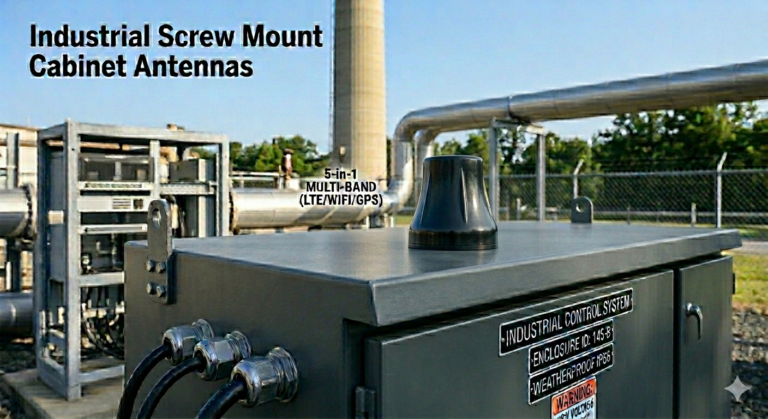
Industrial IoT is a rapidly growing segment for nut antennas. Smart meters, environmental sensors, and remote monitoring systems all need antennas that can survive outdoors for years without maintenance. The nut mounting style provides the mechanical strength needed for long-term deployment.
One interesting application I worked on recently involved smart city infrastructure. A municipal government wanted to install air quality sensors across the city. Each sensor needed a LoRa antenna to transmit data back to a central server. We provided nut-mounted LoRa antennas that could be installed on light poles and building facades. The installation was fast, and the antennas have been operating without any issues for over two years now.
How Do You Install a Nut Antenna Correctly?
Installation might seem straightforward, but I have seen many cases where poor installation led to performance problems. Getting it right the first time saves a lot of trouble later.
To install a nut antenna, drill a hole matching the thread size through a metal surface, pass the threaded base through from the outside, and tighten the mounting nut from the inside. Ensure good metal-to-metal contact for proper grounding. Apply weatherproof sealant around the base to prevent water ingress.

The first step is choosing the right location. The antenna should be mounted on a flat metal surface with enough space around it. Avoid mounting near large metal objects that could block the signal. For vehicles, the center of the roof is usually the best spot. For equipment enclosures, choose a location away from motors and other sources of electrical noise.
Next, mark the center point and drill a hole. The hole size should match the thread diameter of your antenna. For an M6 thread, you typically need a 6.5mm hole. Use a step drill or a regular drill bit. Make sure the hole is clean and free of burrs. Burrs can prevent good electrical contact and may damage the antenna threads.
Before inserting the antenna, clean the mounting surface. Remove any paint, rust, or coating around the hole. The bare metal surface is critical for proper grounding. Some installers use a wire brush or sandpaper for this step. I always recommend this extra effort because it makes a huge difference in signal quality.
Push the antenna through the hole from the outside. On the inside, place a flat washer over the threads, then thread on the mounting nut. Tighten the nut with a wrench. Do not overtighten, as this can damage the threads or crack the antenna base. The goal is a snug fit with good metal contact.
Here is a detailed installation checklist:
| Step | Action | Tools Needed | Common Mistakes to Avoid |
|---|---|---|---|
| 1. Location Selection | Choose flat metal surface, away from obstructions | None | Mounting near large metal structures |
| 2. Hole Drilling | Drill hole matching thread size | Drill, step bit or regular bit | Wrong hole size, rough edges |
| 3. Surface Preparation | Clean mounting area, remove paint/rust | Wire brush, sandpaper | Leaving paint or coating on surface |
| 4. Antenna Installation | Insert antenna from outside, add washer and nut inside | Wrench | Overtightening, cross-threading |
| 5. Weatherproofing | Apply sealant around base | Silicone sealant or rubber gasket | Skipping this step |
| 6. Cable Connection | Connect coaxial cable to antenna base | None (hand tight) | Using excessive force on connector |
| 7. Testing | Check signal strength and VSWR | Spectrum analyzer or signal meter | Skipping functional test |
After mechanical installation, apply weatherproof sealant around the base. Silicone sealant works well for most applications. For marine or extreme environments, consider using a rubber gasket in addition to sealant. This prevents water from seeping into the mounting hole and causing corrosion.
Finally, connect your coaxial cable to the antenna's connector. Most nut antennas use SMA, TNC, or N-type connectors. Hand-tighten the connector first, then use a wrench to snug it up. Do not use excessive force, as this can damage the connector threads.
After installation, test the antenna. Use a signal strength meter or a spectrum analyzer to verify performance. Check the VSWR (Voltage Standing Wave Ratio) to ensure the antenna is properly matched to your system. A VSWR below 2:1 is acceptable for most applications. If the VSWR is higher, check your installation steps again. Poor grounding or a loose connection can cause high VSWR.
What Are the Key Specifications to Consider When Choosing a Nut Antenna?
Choosing the right nut antenna is not just about the mounting style. The electrical specifications determine whether the antenna will work for your application.
When selecting a nut antenna, consider the frequency range, gain, VSWR, impedance, polarization, and connector type. Match these specifications to your wireless system requirements. Also verify the mechanical specifications like thread size, cable length, and environmental ratings to ensure proper fit and durability.

Frequency range is the first thing to check. Every wireless system operates on specific frequencies. A 4G LTE antenna might cover 700-2700 MHz, while a LoRa antenna operates at 868 MHz or 915 MHz depending on your region. The antenna must cover the frequencies your device uses. Using an antenna outside its designed frequency range results in poor performance or no connectivity at all.
Gain measures how well the antenna focuses energy in a particular direction. It is expressed in dBi (decibels relative to an isotropic radiator). Higher gain means more signal strength in the desired direction, but also a narrower radiation pattern. For mobile applications, you usually want an omnidirectional antenna with moderate gain (2-5 dBi). For fixed point-to-point links, higher gain directional antennas (7-15 dBi) may be better.
VSWR indicates how well the antenna is matched to your system. A perfect match would be 1:1, but this is rarely achieved in practice. Most antennas specify VSWR less than 2:1 across their operating frequency range. Lower VSWR means more of your transmitter's power reaches the antenna and radiates. High VSWR causes power reflection, which can damage your transmitter and reduces signal strength.
Here is a comprehensive specification comparison:
| Specification | What It Means | Typical Values | Impact on Performance |
|---|---|---|---|
| Frequency Range | Operating frequencies | 700-2700 MHz (cellular), 2.4-2.5 GHz (WiFi) | Must match your system frequencies |
| Gain | Signal directivity | 2-5 dBi (omnidirectional), 7-15 dBi (directional) | Higher gain = longer range but narrower coverage |
| VSWR | Impedance matching | <2:1 (good), <1.5:1 (excellent) | Lower VSWR = better efficiency |
| Impedance | Characteristic impedance | 50 ohms (standard) | Must match your cable and radio |
| Polarization | Signal orientation | Vertical, horizontal, circular | Must match base station polarization |
| Connector Type | Cable interface | SMA, TNC, N-type | Must match your equipment |
| Cable Length | Attached cable length | 1m, 3m, 5m, 10m | Longer cable = more signal loss |
| Thread Size | Mounting thread | M5, M6, M8 | Must fit your mounting hole |
Impedance is usually 50 ohms for most RF systems. This is the standard for cellular, WiFi, and most wireless communication systems. Your antenna, cable, and radio should all have the same impedance. Mismatched impedance causes signal reflections and power loss.
Polarization describes the orientation of the electromagnetic field. Most mobile antennas use vertical polarization because this matches the polarization of cellular base stations. WiFi routers typically use vertical polarization as well. If your antenna and base station have different polarizations, you lose significant signal strength. Some specialized applications use circular polarization, which works regardless of antenna orientation.
Connector type must match your cable and equipment. SMA connectors are common for small devices and WiFi equipment. TNC connectors provide better performance at higher frequencies and are more robust. N-type connectors are used for high-power applications and outdoor installations. Make sure you know what connector type your equipment uses before ordering.
Cable length affects signal loss. Every meter of cable introduces attenuation, especially at higher frequencies. For 2.4 GHz WiFi, a good quality cable loses about 0.5 dB per meter. At 5 GHz, the loss increases to 0.8 dB per meter or more. Keep cables as short as practical for your installation. If you need a longer cable, consider using a higher quality cable with lower loss.
Environmental ratings tell you where the antenna can be used. IP67 rating means the antenna is dust-tight and can withstand temporary immersion in water. This is suitable for most outdoor applications. Operating temperature range is also important. Standard antennas work from -40°C to +85°C, but some applications may need extended temperature ranges.
What Are Common Problems with Nut Antennas and How to Solve Them?
Even with proper installation, problems can occur. I have helped many clients troubleshoot antenna issues over the years. Most problems have simple solutions if you know what to look for.
**Common nut antenna