I have seen many customers struggle with GNSS signal issues in challenging environments. They buy standard antennas, but these products fail when they need them most. Custom GNSS antenna design solves these real-world problems.
Custom GNSS antenna design requires understanding your specific application needs, selecting the right antenna type, optimizing frequency bands, and testing performance in actual operating conditions. A well-designed custom antenna can improve signal reception by 30-50% compared to standard solutions.

I remember one surveying team that contacted us after their equipment failed under an overpass. Their standard internal antenna could not receive satellite signals in that environment. We designed an external GNSS antenna specifically for their measurement instrument. They successfully completed their bridge survey project. This experience taught me that custom design makes the difference between project success and failure.
What Makes Custom GNSS Antenna Design Different from Standard Products?
Standard GNSS antennas work well in ideal conditions. But real-world applications rarely provide ideal conditions. I have worked with customers who face signal blockage, interference, and extreme weather conditions.
Custom GNSS antenna design addresses specific challenges in your application environment. We analyze your frequency requirements, mounting constraints, cable length needs, and environmental factors to create an antenna that performs optimally in your exact use case.

The main difference lies in the design process itself. Standard products follow a one-size-fits-all approach. Custom design starts with your requirements. I ask customers detailed questions about their application. Where will you mount the antenna? What frequency bands do you need? What environmental challenges will you face? Do you need multi-constellation support?
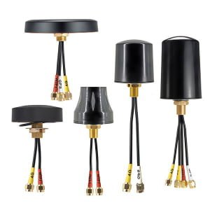
Based on these answers, I can recommend the right antenna type. Patch antennas work well for stationary applications. Helical antennas provide better performance in mobile environments. External active antennas solve problems when you cannot place the antenna in an optimal location.
The customization extends to mechanical design as well. I have designed antennas with special mounting brackets for vehicle roofs. I have created waterproof housings for marine applications. I have even designed antennas that blend into architectural elements for aesthetic requirements.
Here is a comparison of key design factors:
| Design Factor | Standard Antenna | Custom Antenna |
|---|---|---|
| Frequency Bands | Fixed (usually GPS L1) | Selectable (GPS, GLONASS, Galileo, BeiDou) |
| Gain | Typical 3-5 dBi | Optimized 2-10 dBi based on need |
| Size | Standard dimensions | Tailored to mounting space |
| Cable Length | Fixed (usually 3m) | Custom length (1m to 10m+) |
| Connector Type | Standard SMA | Any type required |
| Environmental Rating | Basic IP rating | Specific IP rating for environment |
How Do You Determine the Right Frequency Bands for Your Custom GNSS Antenna?
Frequency selection confuses many customers. They know they need GPS but do not understand the different frequency bands. I explain this in simple terms. GNSS systems broadcast on multiple frequencies. GPS uses L1 and L2 bands. GLONASS has its own frequencies. Galileo and BeiDou add more options.
The right frequency bands depend on your accuracy requirements and the GNSS constellations you want to receive. Single-band antennas (L1 only) work for basic positioning. Dual-band or multi-band antennas enable high-precision applications like RTK surveying and autonomous vehicles.

I start by understanding the customer's accuracy needs. Basic navigation requires only GPS L1 band. This provides accuracy within 5-10 meters. Many consumer applications work fine with this level of precision.
High-precision applications need dual-band capability. Surveying equipment typically uses L1 and L2 bands. This combination allows for error correction and achieves centimeter-level accuracy. The surveying team I mentioned earlier needed dual-band capability to work under the overpass.
Multi-constellation support provides better reliability. I recommend designing antennas that receive GPS, GLONASS, Galileo, and BeiDou signals. More satellites mean better coverage, especially in challenging environments like urban canyons or dense forests.
The frequency requirements also affect antenna size. Lower frequencies need larger antennas. Higher frequencies allow smaller designs. I balance these factors based on the customer's mounting space and performance requirements.
Here is how different applications map to frequency requirements:
| Application Type | Recommended Bands | Typical Accuracy | Antenna Type |
|---|---|---|---|
| Basic Navigation | GPS L1 | 5-10m | Passive Patch |
| Vehicle Tracking | GPS L1 + GLONASS | 2-5m | Active Patch |
| Precision Agriculture | GPS L1/L2 | 0.5-2m | Dual-band Active |
| Survey & Mapping | GPS L1/L2 + Multi-GNSS | 1-5cm | RTK Dual-band |
| Autonomous Vehicles | All GNSS bands | <10cm | Multi-band Active |
What Are the Critical Design Parameters for Custom GNSS Antennas?
Design parameters determine antenna performance. I focus on several key specifications. Gain affects how well the antenna receives weak signals. VSWR indicates how efficiently the antenna converts received signals. Axial ratio matters for circular polarization quality.
Critical design parameters include gain (typically 2-5 dBi for passive, up to 28 dBi for active), VSWR (<2.0 for good performance), axial ratio (<3 dB for circular polarization), and noise figure (<2 dB for active antennas). These parameters must match your application requirements.

Gain represents the antenna's ability to concentrate received signals. Higher gain sounds better, but it is not always necessary. I design passive patch antennas with 3-5 dBi gain for most stationary applications. Mobile applications sometimes need lower gain to maintain signal reception at different angles.
Active antennas include a low-noise amplifier (LNA). The LNA boosts weak signals before they travel through the cable. I typically design active antennas with 20-28 dB of gain. This compensates for cable loss and improves signal-to-noise ratio at the receiver.
VSWR (Voltage Standing Wave Ratio) measures impedance matching. Perfect matching gives VSWR of 1:1. I target VSWR below 2.0 across the operating frequency bands. Better matching means less signal reflection and more efficient signal transfer.
Circular polarization is essential for GNSS antennas. Satellite signals are circularly polarized. The antenna must maintain this polarization to receive signals effectively. Axial ratio measures polarization quality. I design antennas with axial ratio below 3 dB across the operating frequencies.
Here is a detailed parameter breakdown:
| Parameter | Good Performance | Excellent Performance | Impact on System |
|---|---|---|---|
| Gain (Passive) | 2-3 dBi | 4-5 dBi | Signal strength |
| Gain (Active) | 20-25 dB | 26-28 dB | Long cable capability |
| VSWR | <2.5 | <1.5 | Signal efficiency |
| Axial Ratio | <3 dB | <1 dB | Polarization purity |
| Noise Figure (Active) | <2.5 dB | <1.5 dB | Weak signal reception |
| Out-of-Band Rejection | >30 dB | >40 dB | Interference immunity |
How Do Environmental Factors Influence Custom GNSS Antenna Design?
Environmental conditions make or break antenna performance. I have designed antennas for extreme temperatures, high humidity, salt spray, and heavy vibration. Each environment requires specific design considerations.
Environmental factors directly impact antenna materials, housing design, and sealing methods. Marine environments need corrosion-resistant materials and IP67+ waterproofing. Automotive applications require vibration resistance and wide temperature range (-40°C to +85°C). Industrial settings may need explosion-proof housings.

Temperature affects antenna performance in two ways. Extreme temperatures change material properties. Thermal expansion can crack housings or break solder joints. I select materials with similar thermal expansion coefficients. I use temperature-stable ceramics for patch antennas. I specify cables rated for the operating temperature range.
Water is the enemy of electronic devices. I design waterproof housings with proper sealing. IP67 rating protects against temporary immersion. IP68 rating allows continuous underwater operation. The sealing method depends on the application. I use O-rings for removable covers. I use potting compound for permanent sealing.
Vibration matters for mobile applications. Vehicle-mounted antennas experience constant vibration. I use shock-absorbing mounting systems. I specify cables with strong strain relief. I design internal components to withstand vibration testing per automotive standards.
UV radiation degrades plastic materials over time. Outdoor antennas need UV-resistant housings. I use materials like polycarbonate or fiberglass. I add UV stabilizers to plastic formulations. Dark colors absorb more heat but resist UV better than light colors.
Here are environmental design considerations:
| Environment | Key Challenges | Design Solutions | Testing Standards |
|---|---|---|---|
| Marine | Salt spray, humidity, water | Stainless steel, IP68, conformal coating | IEC 60529, ASTM B117 |
| Automotive | Vibration, temperature, shock | Reinforced mounting, wide temp range | ISO 16750, SAE J1455 |
| Industrial | Dust, chemicals, EMI | IP65+, chemical-resistant housing | IEC 60529, ATEX |
| Aerospace | Extreme temp, pressure, radiation | Aerospace-grade materials, special testing | MIL-STD-810, DO-160 |
| Outdoor Fixed | UV, weather, ice | UV-resistant housing, heating element | IEC 60068-2-75 |
What Testing Methods Validate Custom GNSS Antenna Performance?
Testing separates good designs from great designs. I use multiple testing methods to validate antenna performance. Laboratory testing measures electrical parameters. Field testing confirms real-world performance.
Essential testing includes network analyzer measurements for VSWR and gain, anechoic chamber testing for radiation pattern, and field testing with actual GNSS receivers. I also perform environmental testing for temperature, humidity, and vibration to ensure long-term reliability.

Network analyzer testing comes first. I connect the antenna to a vector network analyzer. This measures S-parameters across the frequency range. S11 parameter shows return loss and VSWR. I verify that VSWR stays below specification across all operating frequencies.
Gain measurement requires specialized equipment. I use an anechoic chamber to eliminate reflections. I place the antenna on a rotating platform. I measure received signal strength at different angles. This creates a three-dimensional radiation pattern. I verify that the antenna has the specified gain in the desired direction.
Axial ratio testing measures polarization quality. I use a spinning linear antenna to receive the signal. The axial ratio equals the ratio between maximum and minimum received power as the antenna rotates. Good circular polarization shows minimal variation.
Field testing validates real-world performance. I connect the antenna to a GNSS receiver. I record satellite signal strength (C/N0 ratio) for each visible satellite. I test in different environments. I compare results with reference antennas. The surveying team's overpass challenge became our field test. The custom antenna received 8 satellites under the bridge while the standard antenna received only 2.
Environmental testing ensures reliability. I subject antennas to temperature cycling from -40°C to +85°C. I perform humidity testing at 95% relative humidity. I conduct vibration testing per automotive standards. Only antennas that pass all tests go into production.
Here is my testing protocol:
| Test Type | Equipment Required | Key Measurements | Pass Criteria |
|---|---|---|---|
| Network Analysis | VNA | VSWR, Return Loss, Gain | VSWR <2.0, Gain ±1 dB |
| Radiation Pattern | Anechoic Chamber | 3D Pattern, Axial Ratio | AR <3 dB, Pattern symmetry |
| Active Performance | Spectrum Analyzer | Noise Figure, Gain Flatness | NF <2 dB, ±1 dB flatness |
| Field Test | GNSS Receiver | C/N0, Position Accuracy | C/N0 >40 dB-Hz, <2m CEP |
| Environmental | Climate Chamber | Temp, Humidity, Vibration | No performance degradation |
| Long-term | Field Installation | 1000-hour operation | Stable performance |
How Do You Optimize Cable Length and Connector Selection?
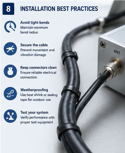
Cable selection affects overall system performance more than many customers realize. I have seen perfect antennas fail because of poor cable choices. The cable carries weak signals from the antenna to the receiver. Any loss in the cable reduces system performance.
Cable length and type must match your installation requirements and signal frequency. RG174 works for short runs (<3m) at lower frequencies. LMR200 or RG58 suits medium lengths (3-5m). LMR400 or equivalent handles longer runs (5-10m) with acceptable loss. Active antennas compensate for cable loss.

Cable loss increases with length and frequency. At GPS L1 frequency (1575 MHz), RG174 cable loses about 1 dB per meter. A 5-meter cable would lose 5 dB of signal. This equals 70% of the signal power. I recommend RG174 only for very short cables (under 2 meters).
LMR200 cable offers better performance. It loses about 0.4 dB per meter at GPS frequencies. A 5-meter cable loses 2 dB, which is much more acceptable. I specify LMR200 for most applications with cable lengths between 3 and 5 meters.
For longer cable runs, I use LMR400 or equivalent low-loss cable. This cable type loses only 0.2 dB per meter. Even a 10-meter cable loses just 2 dB. The tradeoff is cable diameter and stiffness. LMR400 is much thicker and harder to route than RG174.
Active antennas solve the cable loss problem. The built-in amplifier provides 20-28 dB of gain. This compensates for cable loss. I can use longer cables or thinner cables with active antennas. The surveying team's antenna was active, allowing a 5-meter cable without performance loss.
Connector selection depends on the receiver and environmental requirements. SMA connectors are standard for most GNSS applications. I use SMA male connectors on cables by convention. TNC connectors provide better waterproofing for outdoor installations. Some automotive applications use FAKRA connectors. I always confirm the receiver's connector type before finalizing the design.
Here is cable selection guidance:
| Cable Type | Loss at 1.5 GHz | Max Recommended Length | Best Applications | Typical Cost |
|---|---|---|---|---|
| RG174 | ~1.0 dB/m | 1-2m | Internal connections | Low |
| RG58 | ~0.6 dB/m | 2-4m | Short external runs | Low-Medium |
| LMR200 | ~0.4 dB/m | 3-6m | Standard installations | Medium |
| LMR240 | ~0.3 dB/m | 5-8m | Extended runs | Medium-High |
| LMR400 | ~0.2 dB/m | 8-15m | Long distance | High |
| Active Antenna | Compensated | Up to 20m | Any length needed | N/A (in antenna) |
What Are the Common Challenges in Custom GNSS Antenna Design?
I encounter similar challenges across different custom antenna projects. Understanding these challenges helps me design better solutions. Some challenges relate to physics. Others come from manufacturing or cost constraints.
Common challenges include size constraints versus performance requirements, multipath interference in urban environments, maintaining circular polarization across wide frequency bands, balancing cost against performance, and achieving consistent quality in mass production. Each challenge requires specific design strategies.
Size constraints create the biggest challenge. Customers want small antennas with high performance. Physics limits what I can achieve.