I once received a message from a surveying company. Their expensive drones kept drifting during terrain mapping. They blamed the GPS module. But after I checked their setup, the real problem was their antenna. They used a cheap single-frequency patch that could not handle the precise positioning they needed. This mistake cost them weeks of unreliable data and frustrated clients.
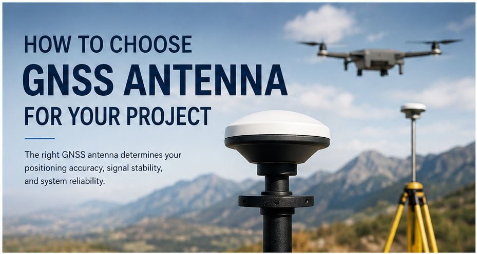
The right GNSS antenna determines your positioning accuracy, signal stability, and system reliability. You need to match antenna type, frequency bands, size, and mounting method to your specific application requirements. Poor antenna choice leads to positioning errors, signal loss, and project delays.
Choosing a GNSS antenna seems straightforward. But I have seen countless projects fail because engineers overlooked critical specifications. The antenna is not just a piece of metal on your device. It captures signals from satellites orbiting 20,000 kilometers above Earth. Every design parameter affects your final positioning performance. Let me walk you through everything you need to know.
What Is a GNSS Antenna and Why Does It Matter?
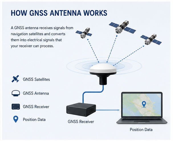
GNSS antennas receive signals from navigation satellites. These signals carry timing information that your receiver uses to calculate position. Without a proper antenna, even the best GNSS module becomes useless.
A GNSS antenna converts electromagnetic waves from satellites into electrical signals your receiver can process. It must capture weak signals across multiple frequency bands while rejecting interference. The antenna's gain, polarization, and phase center stability directly determine your positioning accuracy and system reliability.
Most people think all GNSS antennas work the same way. This is wrong. Different applications demand different antenna technologies. A drone surveying system needs completely different characteristics than a vehicle tracker or maritime navigation device.
The antenna serves as the interface between space and your ground equipment. Satellites transmit signals at power levels around 50 watts. By the time these signals reach Earth, they are incredibly weak. Your antenna must collect these faint signals efficiently while maintaining consistent performance across different satellite elevations and azimuths.
I remember working with a mapping company that used multi-rotor drones for terrain surveying. They needed horizontal accuracy better than 5 centimeters for creating 1:500 scale maps and calculating earthwork volumes. Their original single-frequency antenna could only achieve 3-meter accuracy. The project was failing.
We analyzed their requirements. The drone had strict payload limits. Traditional survey-grade antennas weighed over 100 grams and added too much bulk. This reduced flight time and maneuverability. They needed dual-frequency L1/L5 support, but standard dual-frequency stacked patch antennas were too tall to fit in their compact airframe. The drone's constantly changing attitude also required excellent axial ratio and phase center stability.
We recommended a compact dual-frequency stacked patch antenna that mounted directly on their flight controller board. It weighed only 16 grams. After installation, their positioning accuracy jumped from meter-level to sub-meter level. The reduced weight even extended flight time by about one minute per 10 grams saved. The client was amazed. They could barely feel the weight difference, but the performance improvement was dramatic. This shows how critical proper antenna selection is.
How to Select the Best GNSS Antenna for Your Application?
Every application has unique requirements. A stationary base station operates differently from a moving vehicle or flying drone. Understanding your use case guides every other decision.
Select your GNSS antenna based on application environment, required accuracy, physical constraints, and movement characteristics. Fixed installations can use larger high-gain antennas. Mobile applications need compact, lightweight designs with wide beam patterns. Each use case demands specific trade-offs between size, performance, and cost.
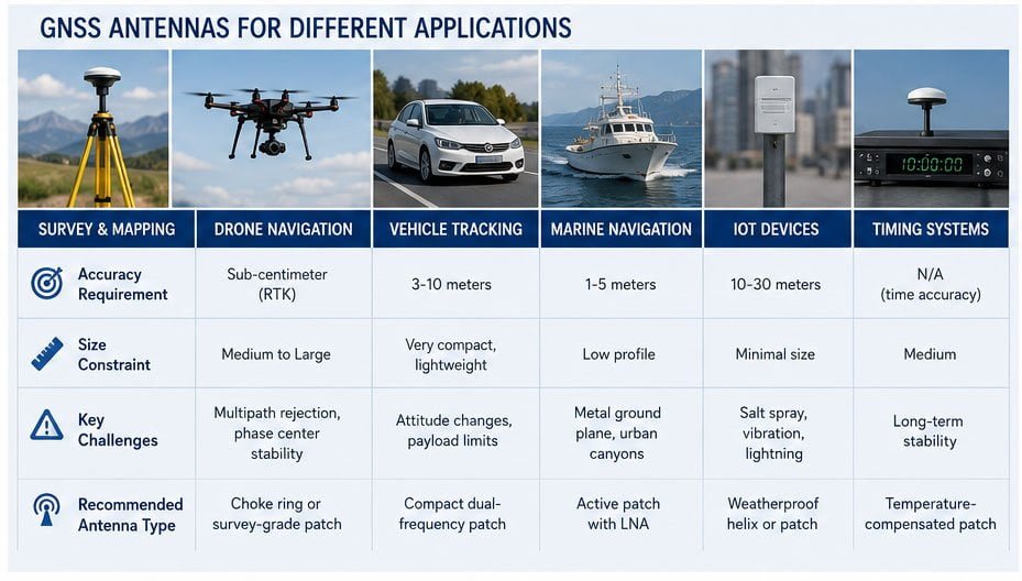
Let me break down the main application categories and their requirements.
Application Type Comparison
| Application Type | Accuracy Requirement | Size Constraint | Key Challenges | Recommended Antenna Type |
|---|---|---|---|---|
| Survey & Mapping | Sub-centimeter (RTK) | Medium to Large | Multipath rejection, phase center stability | Choke ring or survey-grade patch |
| Drone Navigation | Decimeter to Meter | Very compact, lightweight | Attitude changes, payload limits | Compact dual-frequency patch |
| Vehicle Tracking | 3-10 meters | Low profile | Metal ground plane, urban canyons | Active patch with LNA |
| Marine Navigation | 1-5 meters | Weather resistant | Salt spray, vibration, lightning | Weatherproof helix or patch |
| IoT Devices | 10-30 meters | Minimal size | Low power, cost sensitive | Ceramic chip or small patch |
| Timing Systems | N/A (time accuracy) | Medium | Long-term stability | Temperature-compensated patch |
Fixed base stations for RTK correction networks can accommodate larger antennas. These installations benefit from choke ring designs that provide superior multipath rejection. Size and weight are not concerns. Focus shifts to long-term stability and consistent phase center performance.
Mobile mapping vehicles operate in urban environments with significant multipath interference. Buildings reflect GNSS signals, creating ghost echoes that degrade accuracy. You need antennas with good multipath rejection and stable performance at low elevation angles.
Handheld devices face severe size and power constraints. You cannot use a large ground plane. This limits antenna efficiency and increases susceptibility to hand effects and body blockage. Ceramic chip antennas or small patch antennas with integrated LNAs work best here.
Agricultural machinery for precision farming operates outdoors with good sky visibility. These systems need reliable accuracy for automated guidance. Dual-frequency antennas with moderate size work well. Ruggedized housings protect against dust, moisture, and vibration.
Timing applications for telecom base stations or financial trading systems care about time accuracy, not position. These antennas focus on stable group delay and consistent phase characteristics across temperature variations.
I always ask clients these questions first: Where will you use this antenna? Does it move or stay fixed? What accuracy do you need? What are your size and weight limits? These answers immediately narrow down suitable options.
What Frequency Bands Should Your GNSS Antenna Support?
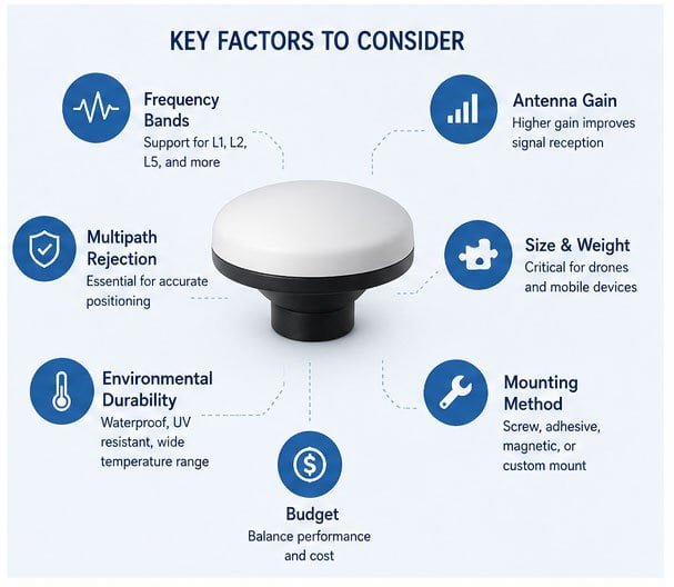
GNSS systems broadcast on multiple frequencies. GPS uses L1 and L5. GLONASS, Galileo, and BeiDou have their own frequency allocations. Your antenna must cover the bands your receiver uses.
Modern GNSS antennas should support multiple frequency bands for better accuracy and redundancy. L1-only antennas provide basic positioning with 3-10 meter accuracy. Dual-frequency L1/L5 or L1/L2 antennas enable sub-meter to centimeter accuracy through ionospheric error correction. Multi-constellation support improves satellite availability in challenging environments.
Let me explain the frequency landscape and why it matters.
GNSS Frequency Bands Overview
| Frequency Band | Center Frequency | GNSS Systems | Primary Use | Accuracy Level |
|---|---|---|---|---|
| L1 | 1575.42 MHz | GPS, Galileo, QZSS | Standard positioning | 3-10 meters |
| L2 | 1227.60 MHz | GPS | Dual-frequency RTK | Centimeter |
| L5 | 1176.45 MHz | GPS, Galileo, QZSS | Safety-critical applications | Sub-meter to centimeter |
| E5a | 1176.45 MHz | Galileo | High accuracy | Centimeter |
| E5b | 1207.14 MHz | Galileo | Commercial service | Decimeter |
| B1 | 1561.098 MHz | BeiDou | Regional service | 3-10 meters |
| B2 | 1207.14 MHz | BeiDou | Open service | Decimeter |
Single-frequency L1 antennas are the most common and affordable. They work fine for basic vehicle tracking or low-cost IoT devices where 3-10 meter accuracy suffices. But L1-only systems suffer from ionospheric delay errors. The ionosphere slows down radio signals. This delay changes with time of day, season, and solar activity.
Dual-frequency antennas solve this problem. By comparing signals on two frequencies, your receiver can calculate and remove most ionospheric error. This improves accuracy to sub-meter or even centimeter level when using RTK corrections. The trade-off is higher cost and larger antenna size.
L5 is the newest GPS signal. It provides better penetration through foliage and urban canyons. L5 has higher transmitted power and wider bandwidth than L1. This makes it more robust against interference and multipath. If your application operates in challenging environments, L5 support is valuable.
Multi-constellation support means your antenna receives GPS, GLONASS, Galileo, and BeiDou simultaneously. This matters in urban canyons or forests where sky visibility is limited. More visible satellites mean better geometry and more reliable positioning. A GPS-only receiver might see four satellites between tall buildings. A multi-constellation system might see twelve. This dramatically improves accuracy and availability.
The frequency requirement directly affects antenna design. Wideband antennas that cover all GNSS bands are larger and more complex than single-band designs. But they offer better future-proofing as new signals come online.
I tell clients to match frequency capability to their accuracy needs. Do not pay for dual-frequency if you only need 10-meter accuracy. But do not skimp on frequency bands if your application demands high precision.
What Antenna Gain and Beam Pattern Do You Need?
Gain measures how well an antenna focuses signal energy. Beam pattern shows where the antenna receives signals from. Both parameters critically affect performance.
GNSS antenna gain typically ranges from -5dBi to +5dBi. Higher gain improves sensitivity but narrows the beam pattern. Fixed installations can use higher gain with narrower beams pointed skyward. Mobile applications need lower gain with wider beam patterns to maintain reception during attitude changes. Match gain and beam width to your movement envelope and required elevation angle coverage.
Understanding gain and patterns requires some physics, but I will keep this practical.
Gain and Pattern Considerations
| Parameter | Low Gain (-5 to 0 dBi) | Medium Gain (0 to +3 dBi) | High Gain (+3 to +5 dBi) |
|---|---|---|---|
| Beam Width | Very wide (>120°) | Moderate (90-120°) | Narrow (<90°) |
| Zenith Sensitivity | Lower | Good | Excellent |
| Horizon Sensitivity | Better | Moderate | Poor |
| Attitude Tolerance | Excellent | Good | Poor |
| Best Use Case | Drones, handheld | Vehicles, portable | Fixed base stations |
GNSS antennas are not omnidirectional. They have maximum sensitivity toward zenith (straight up) and decreasing sensitivity toward the horizon. This makes sense because satellites directly overhead provide the strongest signals and shortest path through the atmosphere.
A typical GNSS patch antenna has about +3dBi gain at zenith and -5dBi at the horizon. The 3dB beam width might be 90 degrees. This means the antenna maintains good sensitivity from zenith down to about 45 degrees elevation. Satellites lower than 45 degrees are received with reduced efficiency.
For fixed base stations, this pattern works perfectly. You want to reject signals from low elevation angles anyway. Low elevation satellites have longer signal paths through the ionosphere and more multipath interference from nearby objects. A high-gain, narrow-beam antenna focused upward maximizes performance.
Mobile applications need wider patterns. Drones tilt and bank during flight. Vehicles navigate slopes and curves. If your antenna has a narrow beam and the platform tilts 30 degrees, you might lose satellites. Wide-beam, lower-gain antennas maintain more consistent reception during movement.
The ground plane size also affects gain and pattern. GNSS antennas need a ground plane to work properly. A larger ground plane increases gain and improves the front-to-back ratio. This reduces interference from signals reflecting off the ground or mounting surface. But larger ground planes add size and weight.
I worked on a project where the client installed high-gain antennas on automated tractors. The tractors worked on hilly terrain with slopes up to 20 degrees. During turns on slopes, the combined tilt sometimes reached 30 degrees. The narrow-beam antennas lost satellite lock. We switched to medium-gain antennas with wider patterns. The slight reduction in peak sensitivity was more than compensated by improved availability during dynamic maneuvering.
How Does Antenna Size and Form Factor Affect Performance?
Physical size directly impacts antenna performance. Larger antennas generally perform better. But many applications have strict size constraints.
Antenna size affects efficiency, gain, and multipath rejection. Larger antennas provide better gain, wider ground planes for multipath suppression, and more stable phase centers. Compact antennas sacrifice performance for portability. The minimum effective antenna size is about one-quarter wavelength. At L1 frequency (1575 MHz), this means roughly 4.8 cm. Smaller antennas require design compromises that reduce efficiency and increase susceptibility to interference.
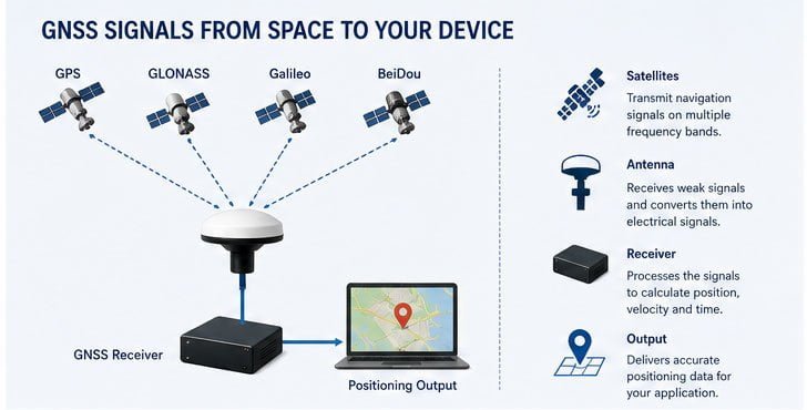
Let me explain the size trade-offs across different antenna types.
Antenna Size and Performance Trade-offs
| Antenna Type | Typical Size | Weight | Gain | Multipath Rejection | Best Application |
|---|---|---|---|---|---|
| Choke Ring | 300-400mm diameter | 2-5 kg | High | Excellent | Permanent base stations |
| Survey Patch | 120-180mm diameter | 300-800g | Medium-High | Very Good | Mobile mapping, construction |
| Standard Patch | 35-50mm square | 50-150g | Medium | Good | General purpose |
| Compact Patch | 25-35mm square | 10-40g | Low-Medium | Fair | Drones, handhelds |
| Ceramic Chip | 10-25mm square | 2-10g | Low | Poor | IoT, wearables |
Choke ring antennas are the gold standard for survey base stations. These large antennas incorporate metal rings around the antenna element. The rings create a choke that prevents surface currents. This dramatically reduces multipath interference from signals reflecting off the mounting structure. Choke rings are heavy and expensive, but nothing beats them for fixed installation accuracy.
Standard patch antennas balance performance and size. A 40mm ceramic patch with proper ground plane provides adequate gain and reasonable multipath rejection. These antennas work well for vehicle tracking, portable surveying equipment, and general navigation applications.
Compact patches shrink the ceramic element to 25-30mm. This reduces weight for drone and handheld applications. The smaller element has lower efficiency and requires a low-noise amplifier (LNA) to maintain adequate sensitivity. The reduced ground plane size increases multipath susceptibility. But for applications where size and weight are critical, compact patches offer acceptable performance.
Ceramic chip antennas integrate everything into a tiny surface-mount component. These antennas are popular in IoT devices and wearables. They require careful PCB layout and ground plane design. Performance is limited, but sufficient for applications needing only rough positioning.
Dual-frequency antennas are inherently larger than single-frequency designs. Supporting two frequency bands requires either two separate elements or a stacked patch configuration. Stacked patches place two resonant elements vertically, increasing antenna height. This added height can be problematic for compact devices.
That drone surveying project I mentioned earlier illustrates these trade-offs perfectly. Traditional survey antennas were too large and heavy. Standard dual-frequency patches were still too bulky. We needed something in between. The 16-gram dual-frequency compact patch we selected was specifically designed for UAV applications. It sacrificed some gain compared to full-size survey antennas, but maintained the dual-frequency capability needed for RTK accuracy.
The client could not believe such a small antenna could deliver professional-grade results. But proper design and careful integration made it work. This is the beauty of understanding the exact requirements and matching the antenna accordingly.
What About Active vs Passive Antennas?
GNSS antennas come in two types. Passive antennas are just the antenna element. Active antennas include a built-in low-noise amplifier (LNA).
Active GNSS antennas contain integrated LNAs that amplify weak satellite signals before transmission through the coaxial cable. They require DC power (typically 3-5V) and provide 25-40dB gain. Active antennas overcome cable losses and improve sensitivity, essential for long cable runs or compact antenna elements with lower efficiency. Passive antennas require external amplification in the receiver. Choose active antennas when cable length exceeds 3 meters or when using compact antenna elements.
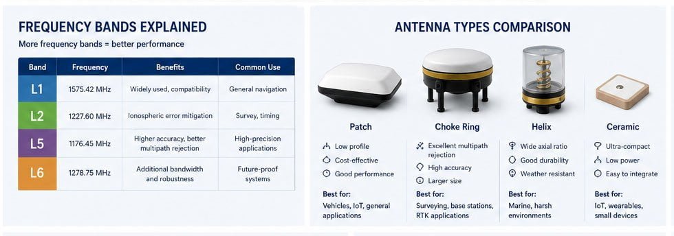
The choice between active and passive affects your system design and performance.
Active vs Passive Antenna Comparison
| Feature | Passive Antenna | Active Antenna |
|---|---|---|
| Built |