I remember when a customer called me, frustrated. He ordered coax cables three times, and none worked. His signal kept dropping. He asked me the same question you might be asking now. The answer changed how he approached his projects.
You need to match the cable's impedance, frequency range, and loss characteristics to your specific application. Start by identifying your system's impedance (usually 50Ω or 75Ω), then check the frequency you're working with, and finally calculate acceptable signal loss over your cable run distance.
Most people think all coax cables are the same. They're not. I've seen projects fail because someone picked the wrong cable. The good news is that once you understand a few basic principles, choosing becomes straightforward. Let me walk you through exactly what I tell my customers.
How to Choose the Right Coaxial Cable for Your Application?
Many people start shopping without knowing their requirements. This leads to expensive mistakes. I've learned that understanding your application first saves time and money later.
Match your cable to your system's impedance (50Ω for RF/cellular, 75Ω for video/broadcast), verify it covers your frequency range, and ensure the cable length won't cause excessive signal loss for your application's tolerance.
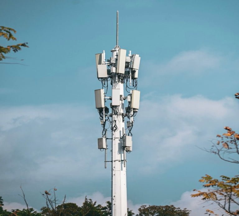
Your application determines everything about your cable choice. I worked with a base station integrator who needed to connect radio units to multi-port antennas. They were using separate cables for each frequency band. The cable runs looked messy. Space was tight. Installation took forever.
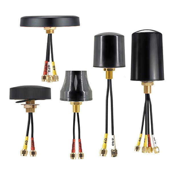
We switched them to bundled coax cable assemblies. These combine multiple RF coaxial cables into one protective jacket with integrated multi-port connectors. Each cable maintains its 50Ω impedance independently. The installation time dropped by 60%. The cable management became clean and professional.
Here's what you should consider for different applications:
| Application Type | Typical Impedance | Frequency Range | Key Consideration |
|---|---|---|---|
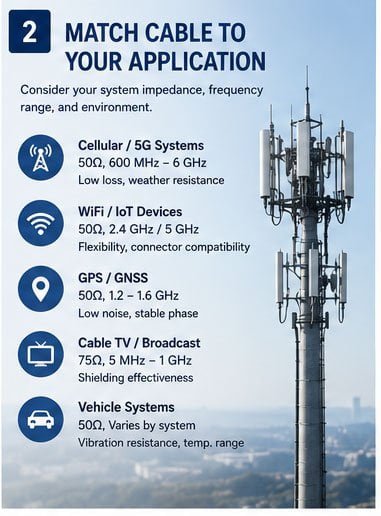
| Cellular/5G Systems | 50Ω | 600 MHz - 6 GHz | Low loss, weather resistance |
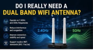
| WiFi/IoT Devices | 50Ω | 2.4 GHz, 5 GHz | Flexibility, connector compatibility |
| GPS/GNSS | 50Ω | 1.2 GHz - 1.6 GHz | Low noise, stable phase |
| Cable TV/Broadcast | 75Ω | 5 MHz - 1 GHz | Shielding effectiveness |
| Vehicle Systems | 50Ω | Varies by system | Vibration resistance, temperature range |
For cellular and RF applications, I always recommend 50Ω cables. For video and broadcast work, 75Ω is standard. Mixing these causes impedance mismatch. That creates signal reflections. Your performance suffers.
What Type of Coax Cable Do You Need? A Complete Guide?
The cable type names can be confusing. RG-58, LMR-400, RG-6. What do these even mean? I'll break down the main types you'll encounter.
You need to understand cable series designations: RG series for general purpose, LMR series for low-loss professional applications, and specialty cables for specific industries. Your choice depends on frequency, power handling, and environmental conditions.
The RG designation comes from an old military standard meaning "Radio Guide." Common types include RG-58 (thin, 50Ω, up to 1 GHz), RG-8 (thick, 50Ω, lower loss), and RG-6 (75Ω, for cable TV). These work fine for basic applications and short runs.
LMR series cables offer better performance. LMR stands for "Low Loss Microwave." LMR-195, LMR-400, and LMR-600 are popular. The number indicates the cable diameter in thousandths of an inch. Larger diameter means lower loss but less flexibility. I use these for professional installations where signal quality matters.
For harsh environments, we offer weatherproof cables with UV-resistant jackets. Some applications need fire-rated cables. Others require extreme temperature tolerance. I once supplied cables for a Middle East project where ambient temperatures exceeded 50°C. Standard cables would have failed. We used specialized high-temperature variants.
Here's a practical breakdown:
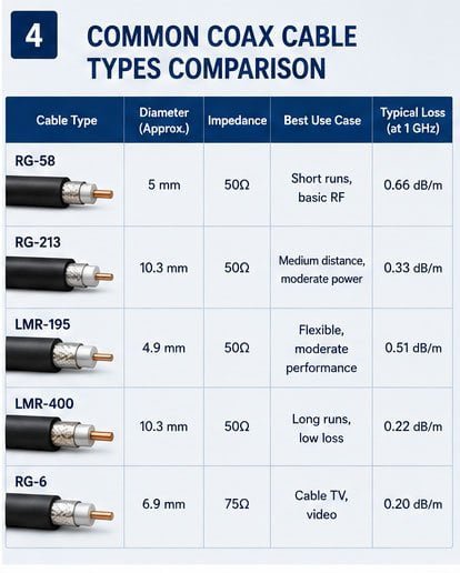
| Cable Type | Diameter | Impedance | Best Use Case | Typical Loss (at 1 GHz) |
|---|---|---|---|---|
| RG-58 | 5mm | 50Ω | Short runs, basic RF | 0.66 dB/m |
| RG-213 | 10.3mm | 50Ω | Medium distance, moderate power | 0.33 dB/m |
| LMR-195 | 4.9mm | 50Ω | Flexible, moderate performance | 0.51 dB/m |
| LMR-400 | 10.3mm | 50Ω | Long runs, low loss | 0.22 dB/m |
| RG-6 | 6.9mm | 75Ω | Cable TV, video | 0.20 dB/m |
For most of my customers doing cellular or WiFi work, I recommend LMR-400 equivalent cables for runs over 3 meters. The lower loss justifies the slightly higher cost. For shorter pigtail connections, LMR-195 offers good flexibility with acceptable loss.
How to Select the Best Coaxial Cable for Your System?
System requirements drive cable selection. I always start by asking customers specific questions about their setup. This prevents ordering the wrong product.
Calculate your total system loss budget, identify your frequency range, determine required power handling, and assess environmental factors. Then select the cable that meets all requirements with margin for safety.
Let me share a real example. A customer was building a 4G LTE router with external antennas. The router's RF port had 50Ω impedance. The antenna was also 50Ω. The cable needed to be 5 meters long. Operating frequency was 700-2700 MHz.
We calculated the system budget. The router output was 23 dBm. The antenna needed at least 20 dBm to maintain good coverage. That gave us a 3 dB loss budget for the cable. At 2.7 GHz, LMR-400 has about 0.27 dB/m loss. Over 5 meters, total loss would be 1.35 dB. Well within budget.
But what if they had used RG-58? At 2.7 GHz, RG-58 loses about 0.9 dB/m. Over 5 meters, that's 4.5 dB total loss. This exceeds the budget. Signal strength at the antenna would be insufficient. Coverage would suffer.
I use this simple calculation formula: Maximum Cable Length (meters) = Loss Budget (dB) ÷ Cable Loss per Meter (dB/m)
Consider these system factors:
| System Factor | Why It Matters | How to Check |
|---|---|---|
| Operating Frequency | Loss increases with frequency | Check device specifications |
| Cable Length | Longer = more loss | Measure actual installation path |
| Power Level | High power needs thicker cables | Check transmitter output power |
| Environmental Exposure | Heat, cold, UV affect cable life | Assess installation location |
| Connector Compatibility | Must match device ports | Identify connector types needed |
| Flexibility Requirements | Installation space may limit cable size | Consider routing path constraints |
For multi-band systems like the base station project I mentioned earlier, we used bundled cable assemblies. Each cable within the bundle was optimized for its specific frequency range. The 2G cables used slightly different specifications than the 5G cables. This modular approach gave us precise control over each signal path.
Coax Cable Buying Guide: How to Make the Right Choice?
Buying from the right supplier matters as much as choosing the right cable. I've seen customers save money initially only to face problems later because they didn't ask the right questions.
Verify the supplier's quality certifications, request detailed specifications and test reports, confirm customization capabilities, check minimum order quantities, and validate lead times before placing orders.
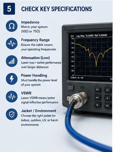
I always recommend asking suppliers these questions before ordering. First, can they provide detailed electrical specifications? Some suppliers only give basic impedance and frequency range. You need to know actual insertion loss at your operating frequency, VSWR across the band, and power handling capacity.
Second, do they have quality certifications? We maintain ISO9001 certification. Our products meet CE and RoHS standards for European markets. These aren't just paperwork. They represent consistent manufacturing processes and material controls.
Third, what's their testing procedure? We test every cable assembly before shipping. We check VSWR, insertion loss, and connector integrity. Some suppliers only spot-check batches. That creates consistency problems.
Fourth, can they customize? Standard cables work for many applications, but sometimes you need specific lengths, connector combinations, or cable types. We've made cables as short as 0.15 meters and as long as 50 meters. We can terminate with virtually any RF connector type.
Here's what to verify before purchasing:
| Verification Item | What to Request | Why It Matters |
|---|---|---|
| Specifications Sheet | Detailed electrical parameters | Ensures cable meets your requirements |
| Test Reports | Actual measured data | Confirms specifications are real, not theoretical |
| Quality Certificates | ISO, CE, RoHS documentation | Indicates consistent manufacturing quality |
| Customization Options | Available lengths, connectors, cable types | Determines if supplier can meet special needs |
| MOQ Flexibility | Minimum order quantities | Important for prototyping and testing |
| Lead Time | Production and shipping duration | Affects project timeline |
| Sample Availability | Test samples before bulk order | Reduces risk of compatibility issues |
I once had a customer order 1000 cables from a new supplier to save 15% on cost. The cables arrived with inconsistent impedance. Half failed VSWR testing. They had to scrap the entire batch and reorder from us. The delay cost them more than they would have saved. Starting with samples would have caught the problem early.
For new customers, I always suggest ordering samples first. Test them in your actual system. Verify the mechanical fit, electrical performance, and build quality. Once you're satisfied, scale up to production quantities.
Choosing the Right Coax Cable: Key Factors to Consider?
Several technical factors determine cable performance. Understanding these helps you make informed decisions. I've simplified the most important ones based on what my customers need to know.
Focus on these critical factors: impedance matching (50Ω or 75Ω), insertion loss at your frequency, shielding effectiveness, connector quality, and environmental rating. Each directly affects system performance.
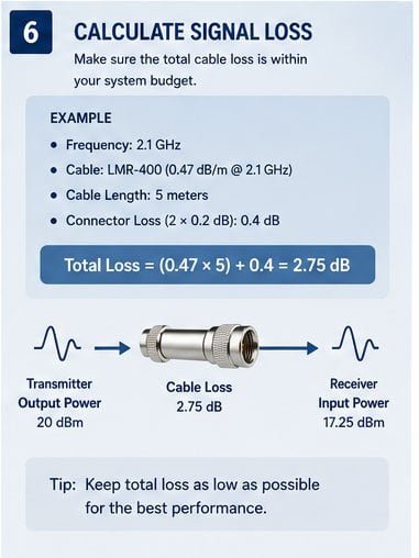
Impedance is the foundation. All components in your RF system must have matching impedance. Using a 75Ω cable in a 50Ω system creates reflections. These show up as poor VSWR (Voltage Standing Wave Ratio). Good systems target VSWR below 1.5:1. Impedance mismatches push VSWR above 2:1 or worse.
Insertion loss tells you how much signal the cable absorbs. This loss increases with frequency and cable length. At 1 GHz, a good quality cable might lose 0.2-0.3 dB per meter. At 5 GHz, the same cable might lose 0.5-0.7 dB per meter. This matters more in receive applications where signals are already weak.
Shielding protects your signal from external interference and prevents your signal from radiating out. Quality cables use double or triple shielding. We use braided copper shields combined with aluminum foil layers. This achieves shielding effectiveness above 90 dB. Cheap cables with single-layer shielding barely reach 60 dB.
I learned this the hard way. A customer installed cables near high-power transmitters. They used budget cables with poor shielding. Interference destroyed their signal quality. We replaced them with triple-shielded cables. Problem solved immediately.
Connector quality matters more than people realize. The connector is where most failures occur. Cheap connectors use thin plating that wears quickly. Contacts become loose. Impedance at the connector varies. We use connectors with heavy gold plating and precise mechanical tolerances. They maintain stable performance through hundreds of connection cycles.
| Factor | What to Check | Target Specification |
|---|---|---|
| Impedance | Nominal value and tolerance | 50Ω ±2Ω or 75Ω ±2Ω |
| Insertion Loss | Loss per meter at operating frequency | Lower is better; <0.3 dB/m at 2 GHz |
| VSWR | Maximum across frequency range | <1.5:1 ideal, <2:1 acceptable |
| Shielding Effectiveness | dB of isolation | >90 dB for critical applications |
| Connector Plating | Material and thickness | Gold plating, 1-3 microns minimum |
| Temperature Rating | Operating range | -40°C to +85°C for outdoor use |
| Flexibility | Minimum bend radius | Smaller = more flexible, but check loss impact |
Environmental rating deserves attention for outdoor installations. UV exposure degrades cheap PVC jackets within months. We use PE (polyethylene) or TPU (thermoplastic polyurethane) jackets for outdoor cables. These materials remain stable for years under direct sunlight.
Temperature range is critical in extreme climates. Standard cables are rated -20°C to +60°C. For outdoor base stations or vehicle installations, you need -40°C to +85°C rating. The cable's dielectric material and jacket must remain stable across this range. We've supplied cables to customers in Saudi Arabia and Norway using the same high-temperature-range specifications.
How to Determine Which Coaxial Cable Is Best for Your Project?
Every project has unique requirements. The "best" cable for one project might be wrong for another. I help customers analyze their specific situation to find the optimal solution.
Evaluate your project by listing all technical requirements, environmental constraints, budget limits, and timeline needs. Then compare cable options against these criteria to identify the best fit, not just the cheapest or highest-spec option.
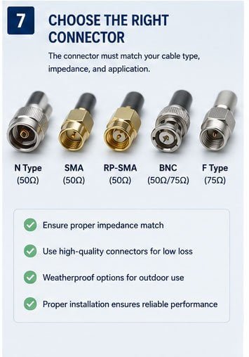
I recently worked with a client developing IoT tracking devices for shipping containers. The project had multiple constraints. First, the devices operated on LTE Cat-M1 (700-900 MHz). Second, the antennas needed 2-meter cables to mount externally while the electronics stayed inside. Third, the cables would face extreme conditions: -30°C in winter shipping, +70°C in summer containers, constant vibration, and occasional water exposure. Fourth, they needed 500 pieces initially, with potential for 10,000+ in production.
We analyzed each requirement. For frequency, both RG-58 and LMR-195 would work technically. For environment, we needed industrial-grade jacketing. For flexibility and durability, LMR-195's smaller diameter and better flex life won out. For quantity, our MOQ of 100 pieces fit their testing phase, and we could scale to their production volume.
The solution was custom LMR-195 cables with reinforced TPU jackets, sealed connectors, and extended temperature rating. We made 50 samples first. They tested for three months in actual shipping routes. Performance remained stable. They ordered production quantities.
Consider these project-specific questions:
| Project Aspect | Questions to Ask | How It Affects Cable Choice |
|---|---|---|
| Technical Requirements | What frequency? What impedance? What loss budget? | Determines cable type and size |
| Installation Environment | Indoor or outdoor? Temperature range? Moisture exposure? | Affects jacket material and sealing |
| Mechanical Requirements | Fixed or mobile installation? Bend radius limits? | Influences cable flexibility and durability |
| Quantity Needs | How many needed? When? | Impacts supplier selection and customization options |
| Budget Constraints | What's the per-unit budget? Total project budget? | Balances performance against cost |
| Timeline | When do you need delivery? Testing time available? | Affects whether you can test samples first |
| Future Scaling | Will volumes increase? Will design change? | Influences standardization decisions |
Sometimes the best cable isn't the highest performance option. It's the one that meets all requirements at the best total cost. Total cost includes the cable price, installation labor, long-term reliability, and warranty support.
I had a customer who insisted on the highest-spec cable for a simple WiFi router application. The cable cost was three times what they needed. I recommended a more appropriate option that met all their technical requirements. They saved