When I first started working with positioning systems over fifteen years ago, customers would ask me about "GPS antennas." Today, that conversation has evolved. The real question isn't just about GPS anymore — it's about GNSS antennas, and understanding the difference can make or break your device's performance in real-world applications.
GNSS (Global Navigation Satellite System) refers to all satellite navigation systems combined — including GPS, GLONASS, Galileo, BeiDou, and others. A GNSS antenna is a specialized RF antenna designed to receive signals from multiple satellite constellations simultaneously, enabling your device to determine precise position, velocity, and timing. Unlike single-system GPS antennas, GNSS antennas capture signals across different frequency bands (L1, L2, L5) from various global and regional satellite networks, delivering faster satellite acquisition, better accuracy, and improved reliability — especially in challenging environments like urban canyons or dense foliage.

You're probably wondering which GNSS antenna actually matches your application requirements, and whether those extra features manufacturers advertise really matter. I've seen countless projects where teams selected the wrong antenna based on price alone, only to discover positioning failures during field testing. Let me walk you through everything you need to know — from understanding how these antennas work to making the right selection for your specific use case.
What is a GNSS Antenna and How Does It Work?
I remember a customer once telling me their "GPS tracker" kept losing signal inside vehicles. The issue wasn't the GPS module — it was their misunderstanding of what modern positioning actually requires.
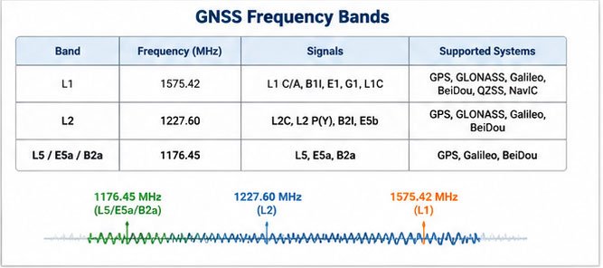
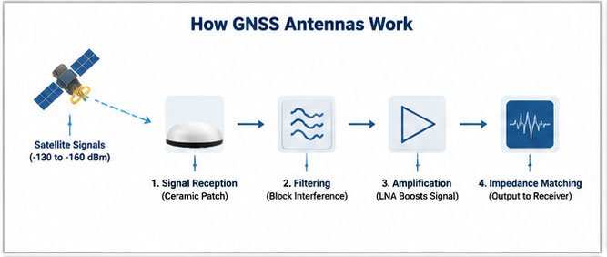
A GNSS antenna is a specialized radio frequency antenna engineered to capture weak satellite signals from space (typically -130 to -160 dBm), filter out interference, and amplify these signals to a level usable by GNSS receivers. Modern GNSS antennas receive signals from multiple satellite systems simultaneously — GPS (USA), GLONASS (Russia), Galileo (Europe), BeiDou (China), and regional systems like QZSS (Japan) and NavIC (India) — operating across multiple frequency bands including L1 (1575.42 MHz), L2 (1227.60 MHz), and L5 (1176.45 MHz).
How GNSS Antennas Capture Satellite Signals
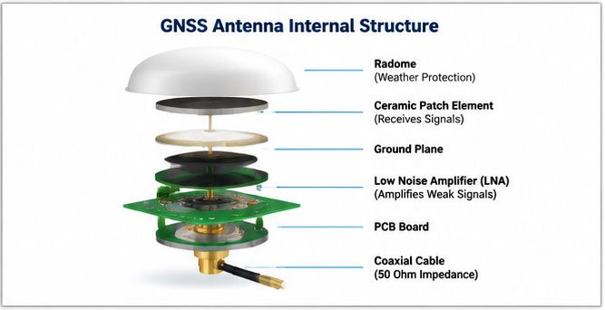
The physics behind GNSS antennas is both elegant and complex. At the core sits a ceramic patch element tuned to resonate at specific GNSS frequencies. This isn't your typical metal antenna — ceramic materials provide superior temperature stability and consistent performance across different climates.
Here's what happens when a satellite signal reaches your antenna:
- Signal Reception: The ceramic patch element receives right-hand circularly polarized (RHCP) signals from satellites orbiting 20,000+ kilometers above Earth
- Filtering: Built-in passive filters block out-of-band interference from cellular networks, Wi-Fi, and other RF sources
- Amplification: An integrated Low Noise Amplifier (LNA) boosts the signal by 20-40 dB, compensating for cable losses and improving signal-to-noise ratio
- Impedance Matching: The antenna converts the received signal to standard 50-ohm impedance for transmission through coaxial cable
The LNA component deserves special attention. I've tested antennas where a cheap LNA created more problems than it solved — introducing noise and consuming excessive current. Quality GNSS antennas use low-noise figure amplifiers (typically 0.8-1.5 dB noise figure) with flat gain across all GNSS bands.
Active vs. Passive GNSS Antennas
In our manufacturing facility, we produce both types, and the choice between them often confuses customers.
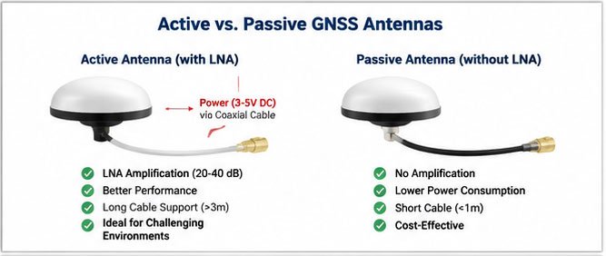
Active GNSS antennas contain integrated LNA circuitry powered through the coaxial cable (typically 3-5V DC). They're essential when:
- Cable runs exceed 3 meters
- The receiver has weak input sensitivity
- You're working in signal-challenged environments
Passive GNSS antennas have no amplification and rely entirely on the receiver's sensitivity. They work best for:
- Short cable connections (under 1 meter)
- Applications where power consumption is critical
- Receivers with excellent front-end sensitivity
In my experience, 85% of commercial applications require active antennas. The small additional cost (typically $2-5 per unit) provides massive benefits in real-world performance.
Multi-Constellation vs. Single-System Antennas
This is where GNSS truly differs from old-school GPS. A traditional GPS antenna only receives L1 signals from US GPS satellites — typically seeing 8-12 satellites at any moment. A modern multi-constellation GNSS antenna receives:
- GPS: 31 satellites (L1, L2, L5 bands)
- GLONASS: 24 satellites (L1, L2 bands)
- Galileo: 30 satellites (E1, E5a, E5b bands)
- BeiDou: 49 satellites (B1, B2, B3 bands)
That's potentially 130+ satellites visible to your device simultaneously. More satellites mean:
- Faster TTFF (Time To First Fix): 15-30 seconds vs. 60+ seconds
- Better accuracy: Sub-meter precision vs. 3-5 meter accuracy
- Improved availability: Reliable positioning in urban canyons, valleys, and partial obstruction scenarios
- Enhanced redundancy: If one constellation has issues, others compensate
I've conducted side-by-side tests in downtown Shenzhen, where GPS-only devices struggled to maintain lock between tall buildings. GNSS antennas with multi-constellation support maintained consistent positioning throughout the same route. The difference is dramatic.
How to Choose the Right GNSS Antenna for Your Application
Last month, an automotive OEM asked me for "the best GNSS antenna." My first question was: "Best for what?" They hadn't considered that dashboard mounting requirements differ completely from roof-mounted systems.
Choosing the right GNSS antenna requires matching five critical parameters to your application: frequency band support (single-band L1 vs. multi-band L1/L2/L5), gain characteristics (typically 26-30 dBi for passive, 38-45 dBi for active), physical form factor (external vs. embedded), environmental protection rating (IP rating for outdoor use), and mounting method (magnetic, adhesive, bolt-down, or embedded). Your selection must balance these factors against cost, size constraints, and performance requirements specific to your deployment environment.
Match Antenna Type to Your Device Category
I've learned that application category is the starting point for any antenna selection:
Consumer IoT Devices (asset trackers, pet trackers, personal navigation):
- Compact size (25-35mm diameter)
- Moderate gain (26-28 dBi)
- Cost-sensitive (target under $3-5 per unit)
- IP65+ rating for basic weather protection
Automotive Applications (telematics, fleet management, ADAS):
- Low-profile design (under 20mm height)
- High temperature tolerance (-40°C to +85°C)
- Excellent multipath rejection
- Vibration resistance
Industrial & Marine (precision agriculture, surveying, marine navigation):
- Ruggedized construction
- Wide voltage input range (3.3V to 18V)
- Survey-grade accuracy (RTK-capable)
- IP67-IP69K protection
Drone & Aviation:
- Ultra-lightweight (under 50 grams)
- Wide bandwidth for multi-frequency
- Hemispherical radiation pattern
- EMI immunity
I once saw a company try to use a consumer-grade tracker antenna in an agricultural drone. The antenna couldn't handle the vibration and temperature cycles — complete failure after just three weeks of testing.
Frequency Band Requirements
This technical decision has significant cost implications. Here's my practical breakdown:
L1-Only Antennas (1575.42 MHz):
- Lowest cost option
- Adequate for basic positioning (3-5m accuracy)
- Suitable for consumer applications
- Limited performance in challenging environments
L1/L2 Dual-Band Antennas (1575.42 MHz + 1227.60 MHz):
- Better ionospheric correction
- Improved accuracy (1-2m)
- Essential for professional applications
- Moderate cost increase (30-50% over L1-only)
L1/L2/L5 Triple-Band Antennas:
- Maximum accuracy potential (sub-meter)
- Full multi-constellation support
- Future-proof for new GNSS signals
- Premium pricing (2-3x cost of L1-only)
In our sales data, about 60% of customers choose L1/L2 dual-band antennas — the sweet spot between performance and cost for most commercial applications.
Form Factor Considerations
The physical design of your antenna dramatically affects both performance and installation feasibility:
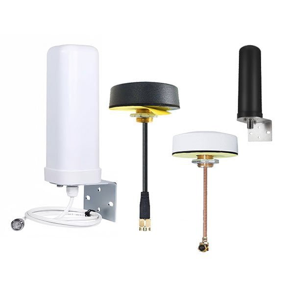
| Form Factor | Size Range | Typical Applications | Key Advantage |
|---|---|---|---|
| Puck/Mushroom | 40-70mm diameter | External mounting, vehicles | Best overall performance |
| Low-profile Patch | 25-40mm, <10mm height | Embedded devices, slim housings | Space efficiency |
| Helical | 15-25mm diameter, 30-50mm tall | Compact devices, handhelds | Omnidirectional pattern |
| Chip/Ceramic | 10-18mm, 2-7mm height | Wearables, miniature IoT | Extreme miniaturization |
| Marine/Survey | 100-200mm diameter | Precision applications | Survey-grade accuracy |
I always advise customers: if space allows, choose the larger antenna. A 50mm patch antenna will consistently outperform a 25mm antenna when both are mounted properly. Physics doesn't negotiate.
Environmental Protection and Durability
Nothing kills a project faster than antenna failures in the field. I've seen this repeatedly:
IP Rating Requirements:
- IP65: Dust-tight, protected against water jets (minimum for outdoor use)
- IP67: Dust-tight, protected against immersion up to 1 meter (standard for most applications)
- IP68: Dust-tight, protected against prolonged immersion (marine and harsh environments)
- IP69K: High-pressure, high-temperature washdown protection (agricultural equipment, food processing)
The jump from IP65 to IP67 costs about $0.50-1.00 per unit in our manufacturing. It's the best insurance you can buy.
Temperature Range:
- Consumer: -20°C to +60°C
- Industrial: -40°C to +85°C
- Automotive: -40°C to +105°C (under direct sun)
- Military/Aerospace: -55°C to +125°C
I've tested antennas that passed bench tests perfectly but failed miserably when exposed to three freeze-thaw cycles. The ceramic patches cracked, the sealant failed, and moisture invaded the LNA circuitry. Always request temperature cycle testing data.
Cable and Connector Selection
This seemingly minor detail causes major headaches. The cable connection between your antenna and receiver is critical:
Cable Types:
- RG174: Thin, flexible, high loss (not recommended over 1.5m)
- RG58: Medium diameter, moderate loss (acceptable for runs up to 3m)
- LMR195: Low loss, good flexibility (preferred for runs up to 5m)
- LMR240/400: Lowest loss, thicker (necessary for runs over 5m)
Connector Types:
- SMA male: Most common, threaded connection
- MMCX: Ultra-compact, snap-on (common in embedded designs)
- TNC: Higher durability, threaded (preferred for vibration environments)
- MCX: Miniature coaxial, snap-on (space-constrained applications)
A common mistake: customers order 5-meter RG174 cables to save $1 per unit. Then they wonder why their positioning accuracy is terrible. That thin cable is losing 3-4 dB over 5 meters — completely negating your antenna's gain. I always recommend LMR195 or better for any cable over 2 meters.
GNSS Antenna Buying Guide: Everything You Need to Know
I've processed over 500 GNSS antenna orders in the past three years, and I can tell you that most purchasing mistakes happen in three areas: specification misunderstanding, quality verification, and supplier evaluation.
When buying GNSS antennas, prioritize these verification steps: request actual test data sheets showing antenna gain patterns, VSWR across all frequency bands, and axial ratio measurements (not just spec sheets); verify the LNA chip model and its specifications (noise figure, gain, current consumption); ask for IP rating test certificates and temperature cycle test reports; evaluate the supplier's production capacity and quality control processes; and negotiate for pre-production samples with your actual cable length and connector type to validate performance in your specific application environment before committing to volume orders.
Understanding Critical Specifications
When I receive RFQs, I often see customers focusing on the wrong specifications. Here's what actually matters:
Antenna Gain: The specification might list "28 dBi" — but gain at which frequency? A well-designed GNSS antenna should show:
- GPS L1 (1575.42 MHz): 26-28 dBi (passive) or 38-42 dBi (active)
- GLONASS L1 (1602 MHz): Similar to GPS L1 ±1 dB
- BeiDou B1 (1561.098 MHz): Within 2 dB of GPS L1
Flat gain across the entire GNSS frequency range (1559-1606 MHz) indicates quality design. If gain varies more than 3 dB across this range, the antenna will favor certain constellations over others — reducing the multi-constellation advantage.
VSWR (Voltage Standing Wave Ratio): This measures impedance matching. Lower is better:
- VSWR < 1.5: Excellent matching (less than 4% power reflection)
- VSWR < 2.0: Acceptable for most applications (11% power reflection)
- VSWR > 2.5: Poor matching (causes signal loss and receiver issues)
I always request VSWR measurements across the full frequency range, not just at center frequency. Some cheap antennas show good VSWR at 1575 MHz but terrible performance at 1560 MHz or 1600 MHz.
Axial Ratio: GNSS signals are right-hand circularly polarized (RHCP). Axial ratio measures how purely circular the antenna's polarization is:
- < 3 dB: Excellent (military/survey grade)
- < 6 dB: Good (commercial grade)
- > 8 dB: Poor (significant signal loss)
An axial ratio of 6 dB means the antenna is losing about 25% of the signal power due to polarization mismatch. In weak signal environments, this difference between 3 dB and 8 dB can mean success versus complete positioning failure.
LNA Specifications (for active antennas): Don't just accept "LNA included" — demand specifics:
- Gain: 25-35 dB (higher isn't always better — can cause saturation)
- Noise Figure: 0.8-1.5 dB (lower is better)
- Current Consumption: 10-25 mA (important for battery-powered devices)
- Input Voltage Range: Should match your receiver's output (typically 3-5V)
I've seen antennas with 45 dB LNA gain that actually performed worse than 28 dB models because the excessive gain saturated the receiver's front end in strong signal areas.
Quality Verification Checklist
Before committing to a supplier, I follow this verification protocol:
Documentation Review:
- Request actual test reports from a qualified antenna test facility
- Verify measurements were conducted in an anechoic chamber, not on a bench
- Check that measurements cover all frequency bands your application requires
- Confirm environmental testing data matches your application conditions
Sample Testing:
- Order samples with your exact cable length and connector type
- Test in your actual device, not on an evaluation board
- Conduct outdoor testing in various environments (open sky, urban canyon, partial obstruction)
- Measure TTFF (Time To First Fix) across multiple cold starts
- Compare satellite count and signal strength (C/N0) against a reference antenna
Field Reliability:
- Request failure rate