I once shipped a batch of RF cables to a European client. Two weeks later, they called me saying the cables did not work. I flew there and found the problem was not the cables but their testing method. That taught me one thing: most people do not know how to test RF cables correctly.
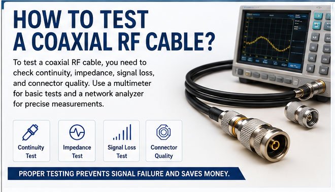
To test a coaxial RF cable, you need to check continuity, impedance, signal loss, and connector quality. Use a multimeter for basic tests and a network analyzer for precise measurements. Proper testing prevents signal failure and saves money.
Testing cables seems simple, but many mistakes happen during the process. I will show you exactly how we test cables in our factory before shipping them to over 100 countries.
How to Check if a Coaxial RF Cable Is Working?
I remember a customer once asked me if his cable was good just by looking at it. I told him that visual inspection is only the first step, not the whole story.
A working coaxial RF cable should have intact connectors, no visible damage, proper continuity between inner and outer conductors, and correct impedance. You can confirm this through visual inspection, continuity testing, and signal transmission tests.
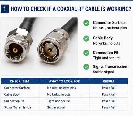
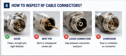
Before you use any tool, start with your eyes and hands. I always tell my team to check three things first: the connector surface, the cable body, and the connection tightness.
Look at the connector. If you see rust, bent pins, or loose threads, the cable is already compromised. Touch the cable body. Feel for any hard spots, kinks, or cuts in the outer jacket. These signs mean the internal structure is damaged.
Next, plug the cable into your device. Does it fit snugly? A loose connection causes intermittent signals. I have seen too many customers blame the cable when the real problem was a worn-out port.
After visual checks, try a simple transmission test. Connect the cable between a signal source and receiver. If the signal drops or disappears, the cable has internal issues. But if the signal passes, you still need more tests to confirm the cable's true performance.
| Check Item | What to Look For | Result |
|---|---|---|
| Connector Surface | No rust, no bent pins | Pass/Fail |
| Cable Body | No kinks, no cuts | Pass/Fail |
| Connection Fit | Tight and secure | Pass/Fail |
| Signal Transmission | Stable signal | Pass/Fail |
This basic check takes less than five minutes but saves hours of troubleshooting later.
How to Test an RF Coaxial Cable with a Multimeter?
One of our production workers once asked me why we could not just use a multimeter for all cable tests. I explained that a multimeter is good for basic checks but cannot measure everything.
A multimeter can test the continuity and resistance of an RF coaxial cable. Set the multimeter to resistance mode, then measure between the center pin and outer shield. A reading close to zero indicates a short circuit, while infinite resistance shows an open circuit. Both mean the cable is faulty.
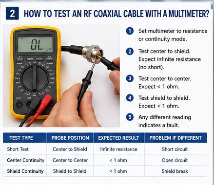
I use a multimeter every day in our factory. It is fast and reliable for finding obvious faults. Here is how I do it step by step.
First, turn off all equipment. Disconnect the cable from both ends. This is important because active signals can damage your multimeter.
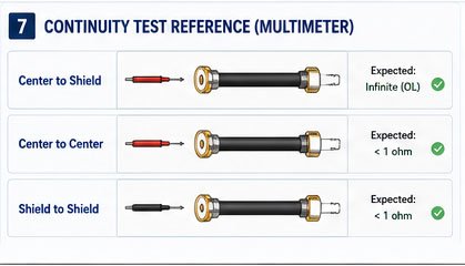
Set your multimeter to the continuity or resistance mode. Some multimeters beep when they detect continuity. Touch one probe to the center conductor and the other probe to the outer shield. You should see infinite resistance or no beep. If you get a low reading or a beep, the cable has a short circuit inside.
Now test the center conductor alone. Touch one probe to the center pin on one end and the other probe to the center pin on the other end. You should see very low resistance, usually less than one ohm. If you see infinite resistance, the center conductor is broken.
Repeat this for the outer shield. Touch one probe to the shield on one end and the other probe to the shield on the other end. Again, you should see very low resistance. High resistance means the shield has a break.
| Test Type | Probe Position | Expected Result | Problem if Different |
|---|---|---|---|
| Short Test | Center to Shield | Infinite resistance | Short circuit |
| Center Continuity | Center to Center | < 1 ohm | Open circuit |
| Shield Continuity | Shield to Shield | < 1 ohm | Shield break |
A multimeter cannot measure signal loss or impedance, but it quickly finds broken or shorted cables. I always keep one in my pocket during factory inspections.
How to Troubleshoot a Coaxial RF Cable?
Last month, a distributor in the Middle East complained about random signal drops. We sent them new cables, but the problem remained. I walked them through troubleshooting, and we found the issue was not the cable at all. It was their installation method.
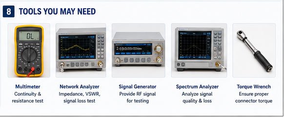
To troubleshoot a coaxial RF cable, isolate the problem by testing each component separately. Check the connectors first, then the cable body, and finally the equipment. Use a signal generator and spectrum analyzer to identify where the signal degrades.
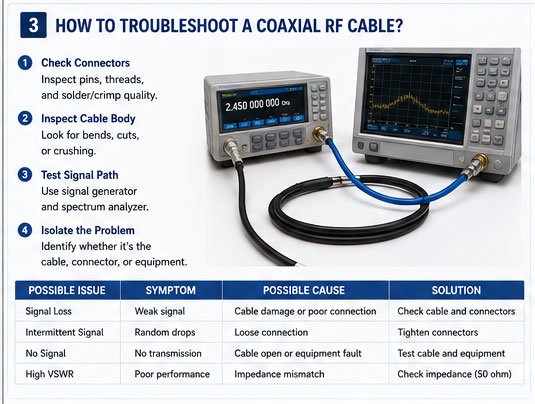
Troubleshooting is like detective work. You eliminate suspects one by one until you find the real culprit. I follow a systematic approach that works every time.
Start with the connectors. Unscrew them and inspect the center pin alignment. I have seen countless cases where the pin was slightly bent, causing poor contact. Also check if the connector is properly crimped or soldered. A weak connection creates signal reflections.
If the connectors look good, inspect the cable along its entire length. Look for sharp bends. RF cables have a minimum bend radius, usually about ten times the cable diameter. Bending too sharply damages the inner structure and changes the impedance.
Next, check the installation environment. Is the cable near high-power motors, fluorescent lights, or other RF equipment? These sources create interference. Also, look for points where the cable is pinched or crushed. Even if the outer jacket looks fine, internal damage can occur.
Now test the cable in a different system. If the problem disappears, the issue is with the original equipment, not the cable. If the problem persists, the cable is likely faulty.
Use a spectrum analyzer if available. Connect it to one end and a signal generator to the other. Sweep through the frequency range. You should see a smooth response. If you see dips or spikes, the cable has impedance discontinuities.
| Troubleshooting Step | What to Check | Action if Problem Found |
|---|---|---|
| Connector Inspection | Pin alignment, crimping | Replace connector |
| Cable Bend Check | Sharp bends, kinks | Reroute cable |
| Environment Check | Interference sources | Move cable |
| System Test | Different equipment | Identify faulty component |
| Frequency Sweep | Impedance discontinuities | Replace cable |
This method has helped me solve hundreds of cable problems. The key is patience and systematic elimination.
How to Identify a Faulty RF Coaxial Cable?
I once had a customer insist that our cables were defective. After three rounds of testing, we proved the cables were perfect. The real problem was corrosion in his equipment's connector port. That experience taught me that fault identification requires both testing and experience.
A faulty RF coaxial cable shows symptoms like high signal loss, impedance mismatch, physical damage, or intermittent connections. You can identify these faults through visual inspection, electrical testing, and performance measurement under operating conditions.
Identifying faults is both science and art. Some problems are obvious, others hide beneath the surface. I have learned to look for specific signs that reveal cable condition.
Physical damage is the easiest to spot. Look for cuts, abrasions, or exposed inner conductors. Check if the cable is flattened or has been repeatedly bent in the same spot. These areas develop stress fractures over time.
Connector quality is critical. A loose connector or one with visible oxidation will degrade performance. I always wiggle the connector gently. If it moves excessively, the internal crimping has failed.
Electrical faults require testing. High resistance in the center conductor or shield indicates corrosion or a partial break. A short between center and shield means the dielectric has failed.
Signal loss is harder to detect without tools. If your system worked before but now has reduced range or weaker signals, the cable might be degrading. This happens slowly over years of exposure to UV, moisture, or temperature cycles.
Intermittent faults are the most frustrating. The cable works sometimes but fails randomly. This usually means a connector is making poor contact or the cable has a hairline fracture that opens and closes with movement.
I keep detailed records of every cable failure in our factory. After 17 years, I have seen patterns. Outdoor cables fail most often at the connectors due to water ingress. Indoor cables fail from repeated flexing. Knowing these patterns helps me identify faults faster.
| Fault Type | Symptoms | Common Cause | Detection Method |
|---|---|---|---|
| Physical Damage | Visible cuts, kinks | Improper handling | Visual inspection |
| Connector Failure | Loose fit, oxidation | Age, moisture | Physical check, resistance test |
| Dielectric Breakdown | Short circuit | Overvoltage, age | Multimeter test |
| Signal Loss | Weak signal, reduced range | Cable degradation | Signal measurement |
| Intermittent Fault | Random failures | Poor contact, fracture | Movement test, monitoring |
When I train new engineers, I tell them to trust their measurements but also use common sense. A cable might test fine electrically but still fail in real-world conditions.
How to Measure the Performance of a Coaxial RF Cable?
A telecommunications company once bought 5000 meters of cable from us. Before accepting delivery, they tested random samples for performance. That is standard practice for serious buyers. They want to know exactly what they are getting.
To measure the performance of a coaxial RF cable, you need to test its insertion loss, return loss, and VSWR across its operating frequency range. Use a vector network analyzer (VNA) for accurate measurements. These parameters determine how well the cable transmits signals.
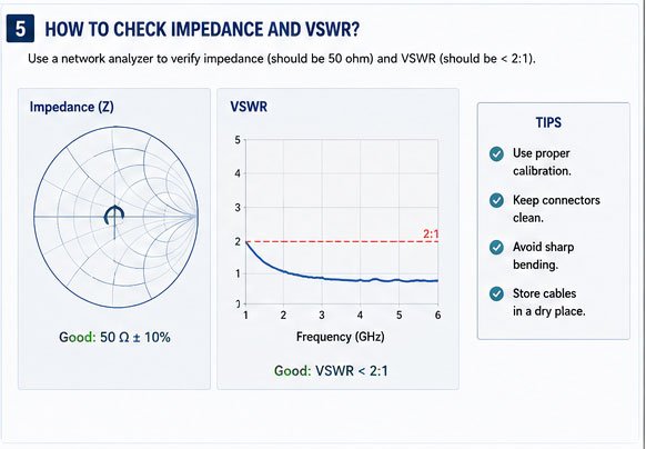
Performance measurement separates good cables from mediocre ones. In our factory, we test every cable type before it goes into production. This ensures consistency.
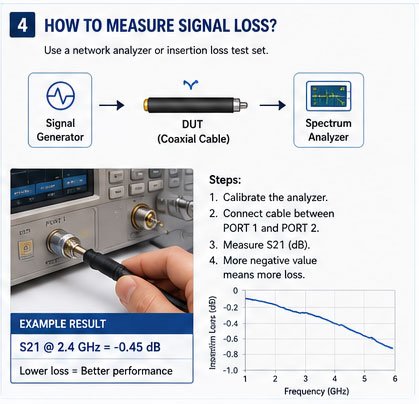
Insertion loss is the most important parameter. It tells you how much signal the cable absorbs. We measure it in decibels per meter. A lower number is better. For example, our RG58 cable has about 0.4 dB/m loss at 1 GHz. At higher frequencies, the loss increases.
To measure insertion loss, connect the cable between two ports of a VNA. The VNA sends a signal through the cable and measures what comes out the other end. The difference is the insertion loss.
Return loss measures how well the cable's impedance matches the system impedance. Poor matching creates reflections that waste power and distort signals. We aim for return loss better than 15 dB across the operating band.
VSWR (Voltage Standing Wave Ratio) is another way to express impedance matching. A perfect cable has a VSWR of 1:1. In practice, we accept 1.5:1 or better. The VNA calculates VSWR from the return loss measurement.
Frequency matters enormously. A cable that performs well at 1 GHz might be terrible at 6 GHz. We always test across the full frequency range the customer will use.
Temperature also affects performance. Some customers require testing at extreme temperatures. We have an environmental chamber that can simulate -40°C to +85°C. Cable loss increases slightly at higher temperatures.
| Performance Parameter | What It Measures | Typical Value (RG58 @ 1GHz) | Tool Required |
|---|---|---|---|
| Insertion Loss | Signal attenuation | 0.4 dB/m | VNA |
| Return Loss | Impedance matching | > 20 dB | VNA |
| VSWR | Standing wave ratio | < 1.3:1 | VNA |
| Characteristic Impedance | Cable impedance | 50 Ω ±2Ω | VNA or TDR |
After 17 years of manufacturing, I can estimate cable performance just by feeling its construction. But I always verify with measurements. Numbers do not lie.
How to Verify the Integrity of an RF Coaxial Cable?
A few years ago, we received a complaint that our cables failed after six months of outdoor use. We investigated and found that the customer had used indoor-rated cables outside. The sun's UV radiation had degraded the jacket, allowing moisture to penetrate. Integrity verification should happen before installation and periodically thereafter.
To verify the integrity of an RF coaxial cable, perform a combination of visual inspection, electrical testing, and environmental stress testing. Check for physical damage, measure electrical parameters, and simulate operating conditions. This ensures the cable will perform reliably over its intended lifespan.
Integrity verification is about proving the cable will survive in the real world. Laboratory tests are just the beginning. We also need to think about aging, weather, and mechanical stress.
Visual inspection comes first. I examine the outer jacket for cracks, discoloration, or brittleness. These signs mean the material has begun to degrade. I also check the flexibility. A cable that has become stiff has likely suffered UV or chemical damage.
Next, I test electrical integrity. I measure DC resistance, capacitance, and insulation resistance. These parameters should match the cable specifications. Any significant deviation suggests internal damage.
Water resistance is critical for outdoor cables. We have a water immersion test where we submerge cables for 24 hours, then measure insulation resistance. It should remain above 5000 megohms. Lower values mean water has penetrated.
Mechanical integrity matters too. I bend the cable repeatedly to its minimum radius and check for changes in electrical performance. A good cable shows no degradation after 1000 flex cycles.
For long-term reliability, we run accelerated aging tests. We place cables in an environmental chamber at 85°C and 85% humidity for 1000 hours. This simulates years of outdoor use. After the test, the cable should still meet all electrical specifications.
I also verify the connector attachment. Pull on the connector with 50 newtons of force. It should not separate from the cable. We have had cases where poorly crimped connectors pulled off under tension.
Finally, I test the cable under power. Some dielectric materials break down under high RF power. We run a high-power test at twice the rated power for one hour. The cable should show no heating, arcing, or performance change.
| Integrity Test | Purpose | Acceptance Criteria | Frequency |
|---|---|---|---|
| Visual Inspection | Detect physical damage | No visible defects | Before installation, quarterly |
| DC Resistance | Verify conductor continuity | Within specification ±5% | Installation, annually |
| Insulation Resistance | Check dielectric integrity | > 5000 MΩ | After environmental exposure |
| Flex Test | Assess mechanical durability | No electrical change after 1000 cycles | Before product release |
| Aging Test | Predict long-term reliability | Meet specs after 1000 hrs @ 85°C/85%RH | Product qualification |
In our factory, every cable batch undergoes integrity testing. We cannot afford to ship products that will fail in the field. Our reputation depends on it.
How to Inspect a Coaxial Cable for Signal Loss?
I received a panicked call from a customer last year. Their new base station had 3 dB more loss than expected. We traced it back to a damaged cable where a construction crew had accidentally driven over it. Signal loss inspection would have caught this before the system went live.
To inspect a coaxial cable for signal loss, measure the insertion loss using a VNA or signal generator with a spectrum analyzer. Compare the measured loss to the cable's datasheet specification. Excessive loss indicates damage, contamination, or poor connector installation.
Signal loss is insidious. You cannot see it or feel it, but it slowly degrades your system performance. I have developed a routine for loss inspection that works whether you have expensive test equipment or just basic tools.
If you have a VNA, the measurement is straightforward. Connect the cable between the VNA ports and measure S21 (transmission). This gives you the insertion loss directly. Compare it to the manufacturer's datasheet. For example, our LMR400 cable should have about 0.22 dB/m loss at 2 GHz. If you measure 0.35 dB/m, something is wrong.
Without a VNA, you can use a signal generator and spectrum analyzer. Set the generator to a known frequency and power level. Connect it through the cable to the