I have seen countless projects fail because of one overlooked issue: interference. Your outdoor antenna might have perfect specifications on paper, but signal disruption will destroy performance in real-world conditions. This creates connection drops, data loss, and frustrated customers.
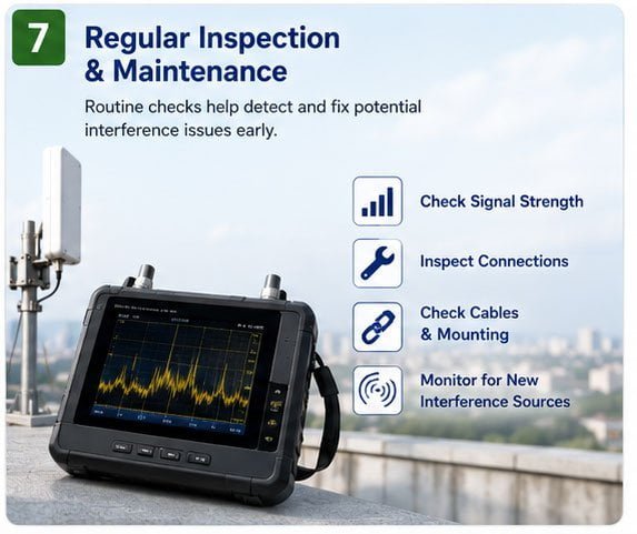
The real solution starts with proper shielded antenna design, not just installation tricks. We use multi-layer shielding, built-in filtering, and high-isolation directional structures in our outdoor RF antennas to block interference at the source. Good installation helps, but hardware protection is what truly matters for stable wireless communication.
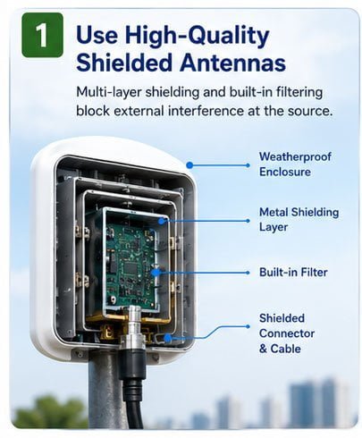
I have worked with outdoor antennas for over 17 years at our Shenzhen facility. We manufacture communication antennas for charging stations, drones, base stations, and industrial IoT projects across 100+ countries. Most interference problems I see come from weak antenna design, not just poor placement.
How to Reduce Signal Interference in Outdoor Antenna Systems?
Signal interference destroys your outdoor antenna performance faster than any other factor. You install a perfectly good antenna, and suddenly your connection becomes unstable. I see this happen repeatedly with clients who focus only on frequency specs but ignore interference protection.
Use antennas with built-in multi-layer shielding and proper filtering circuits. This blocks external electromagnetic noise before it reaches your signal path. Also maintain at least 3 meters distance from power lines, transformers, and metal structures that reflect or distort RF signals.
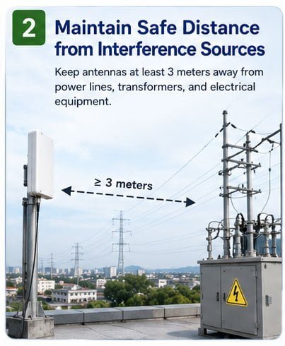
Outdoor environments are electrically noisy. You have power lines generating 50Hz/60Hz harmonics, switching power supplies creating broadband noise, and other wireless systems transmitting on nearby frequencies. Your antenna sits in the middle of this electromagnetic mess.
I design our outdoor antennas with three protection layers. The first layer uses a metal shield around the antenna element itself. This blocks near-field interference from nearby sources. The second layer adds filtering components at the feed point. These filters reject out-of-band signals before they enter your receiver. The third layer uses directional antenna patterns with high front-to-back ratio. This means your antenna "sees" signals mainly from one direction and ignores interference from other directions.
Here is a comparison of different interference reduction methods:
| Method | Effectiveness | Cost Impact | Implementation Difficulty |
|---|---|---|---|
| Multi-layer shielding | Very High | Medium | Must be built into antenna |
| Built-in filtering | High | Medium | Requires proper design |
| Directional pattern | Medium-High | Low | Depends on antenna type |
| Physical separation | Medium | Low | Limited by installation constraints |
| External filters | Low-Medium | High | Adds insertion loss |
| Cable quality | Medium | Low-Medium | Easy to implement |
We tested these methods with our 4G/5G base station antennas deployed near high-voltage transmission lines. The antennas with multi-layer shielding maintained signal quality, while standard antennas showed 15-20dB degradation in signal-to-noise ratio. This difference means the protected antennas worked reliably, and the unprotected ones kept dropping connections.
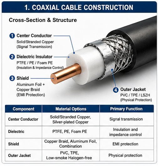
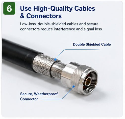
Your cable choice matters too. We only use double-shielded or quad-shielded coaxial cables with proper connector crimping. Low-quality cables with loose braiding let interference leak in through the cable, even if your antenna has good shielding. I once diagnosed a customer's interference problem that turned out to be cheap cable, not the antenna.
How to Avoid Interference When Installing Outdoor Antennas?
Installation location determines how much interference your antenna will face. You can have the best antenna design, but wrong placement will still cause problems. I review hundreds of installation photos from customers every year, and poor location choice creates most of their interference issues.
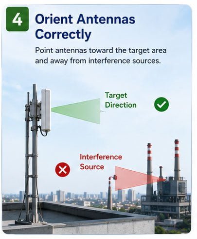
Mount your antenna at least 3 meters away from power lines, fluorescent lights, and switching power supplies. Position it 1 meter above the roofline to clear obstacles. Orient directional antennas away from known interference sources like industrial equipment or broadcast towers on adjacent frequencies.
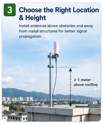
Physical separation is your first defense against interference. The inverse square law means interference power drops by 4 times when you double the distance from the source. Moving your antenna from 1 meter to 2 meters away from a noise source reduces that interference by 6dB. Moving from 1 meter to 4 meters gives you 12dB reduction.
I worked on a charging station project where the customer installed 4G antennas only 50cm from the charging unit. The switching power supply inside the charger created massive broadband noise. The antennas could barely maintain connection. We moved the antennas 3 meters away on an extended pole, and suddenly connection became stable. Same antennas, same site, just better placement.
Here are the critical installation factors:
| Factor | Requirement | Reason |
|---|---|---|
| Distance from power cables | >3 meters | Reduces 50Hz/60Hz harmonic interference |
| Height above obstacles | >1 meter | Clears near-field reflections |
| Proximity to metal | >0.5 meters | Prevents detuning and pattern distortion |
| Orientation accuracy | ±5 degrees | Maximizes desired signal, minimizes interference |
| Ground plane quality | >0.3 wavelength | Ensures proper radiation pattern |
| Cable routing | Away from power lines | Prevents common-mode interference |
You also need to think about future changes. A tree that is small today will grow and create interference in two years. A new building might go up and reflect signals. I tell customers to photograph the area around the installation and note any planned construction. This helps predict future interference problems.
Vertical separation helps more than horizontal separation for some interference types. If you have interference from ground-level sources like vehicle ignition systems, mounting your antenna higher reduces the problem significantly. We mounted IoT gateway antennas at 6 meters height in a port facility, and vehicle interference dropped by 20dB compared to 2-meter mounting height.
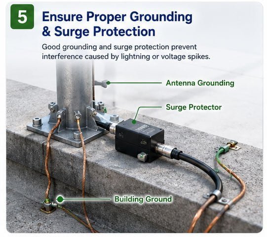
Grounding is often forgotten but critical. Your antenna and cable shield must connect to a proper RF ground, not just any metal pole. We use low-impedance grounding straps (less than 10cm) to connect the antenna mount to the building ground system. This prevents ground loops that allow interference to enter through the cable shield.
What Causes Interference in Outdoor Antennas and How to Prevent It?
Interference comes from dozens of sources in outdoor environments. Understanding what creates interference helps you prevent it effectively. I spent years tracking down interference sources for customer installations, and certain patterns repeat everywhere.
The main outdoor interference sources are: power line harmonics, switching power supplies, plasma noise from electrical arcs, other wireless transmitters, and atmospheric noise. You prevent these by using shielded antennas, proper filtering, careful frequency selection, and adequate physical separation from known noise sources.
Power systems create the most widespread interference. Every power line acts as an antenna that radiates harmonics of the 50Hz or 60Hz main frequency. High-voltage lines are worse because they create corona discharge, which generates broadband noise from DC to several GHz. I measured power line interference 100 meters from a transmission line that was still 30dB above the noise floor at 900 MHz.
Switching power supplies are everywhere now. Solar inverters, LED drivers, variable frequency drives, EV chargers, and laptop power bricks all use switch-mode conversion. These create sharp switching edges that generate harmonics across the entire RF spectrum. A single cheap LED streetlight can interfere with antennas within 10 meters.
Here is a breakdown of common interference types:
| Interference Source | Frequency Range | Typical Strength | Prevention Method |
|---|---|---|---|
| Power line harmonics | DC to 1 GHz | -50 to -20 dBm | Shielding + distance |
| Switching supplies | 100 kHz to 3 GHz | -40 to -10 dBm | Filtering + shielding |
| Plasma/arcs | Broadband | -30 to 0 dBm | Distance + directional antenna |
| Other transmitters | Specific bands | -60 to +30 dBm | Frequency coordination + filtering |
| Atmospheric noise | Below 50 MHz | Variable | Limited prevention options |
| Ignition systems | 10 MHz to 1 GHz | -50 to -20 dBm | Distance + shielding |
Wireless transmitters create interference too, even when they are supposed to coexist. A 4G base station might interfere with nearby GPS receivers because of imperfect transmitter filtering. The 4G signal is so strong that even -60dB suppression at GPS frequencies still creates interference. We solved this for a customer by adding a GPS bandpass filter with 80dB rejection of 4G frequencies.
Intermodulation is a hidden interference source. When two strong signals mix in any nonlinear device (including corroded connectors), they create new signals at sum and difference frequencies. We diagnosed a case where 900 MHz and 1800 MHz signals were creating a false signal at 2700 MHz that interfered with a 2.6 GHz LTE band. The fix required better cable connectors and increased separation between antennas.
Atmospheric noise dominates at lower frequencies. Below 50 MHz, you cannot escape it. Lightning strikes create broadband pulses that propagate thousands of kilometers. Solar activity increases atmospheric noise across all frequencies. For HF applications, we use antennas with narrow bandwidth and high directivity to minimize atmospheric noise reception from unwanted directions.
I learned that preventing interference requires a system approach. You need good antenna design, proper installation, clean power for your receiver, quality cables, and correct frequency selection. Fixing just one element rarely solves the problem completely.
How to Improve Outdoor Antenna Performance by Minimizing Interference?
Better antenna performance comes from reducing interference, not just increasing signal strength. I see customers chase higher antenna gain while ignoring interference, and their systems still fail. Signal-to-noise ratio matters more than raw signal strength for reliable communication.
Maximize your signal-to-interference ratio by using high-gain directional antennas pointed at your desired signal, notch filters to remove specific interference frequencies, and proper antenna polarization matching. Measure actual interference levels before and after changes to confirm improvement rather than guessing.
Directivity is your most powerful interference reduction tool. A directional antenna with 15dBi gain in the forward direction typically has 20-30dB rejection in the rear direction. This means interference from behind is 100 to 1000 times weaker than if you used an omnidirectional antenna. For point-to-point links, we always recommend directional antennas on both ends.
Polarization discrimination helps with certain interference types. If your desired signal uses vertical polarization and the interference uses horizontal polarization, a properly installed vertical antenna will reject that interference by 20-40dB. I fixed interference problems for several WiFi deployments just by ensuring correct antenna polarization orientation and separation between vertical and horizontal polarized antennas.
Here are the key performance improvement techniques:
| Technique | Typical Improvement | Application Scenario | Implementation Cost |
|---|---|---|---|
| Directional antenna | 15-25 dB | Fixed direction links | Low |
| Polarization matching | 20-40 dB | Cross-polarized interference | Free |
| Notch filtering | 30-60 dB | Single strong interferer | Medium |
| Spatial diversity | 3-10 dB | Multipath/fading | Medium |
| Frequency hopping | Variable | Multiple weak interferers | High |
| Antenna separation | 6-20 dB | Co-located systems | Low |
Frequency selection is critical but often overlooked. Many wireless bands have "cleaner" and "noisier" channels. We always perform a spectrum scan before deploying antennas to identify which channels have less interference. A difference of 40 MHz in frequency can mean 20dB less interference in urban environments.
Physical antenna diversity helps in complex interference environments. Using two or more antennas separated by several wavelengths allows the receiver to select the antenna with better signal-to-interference ratio at any moment. We implement this for IoT gateways in industrial environments where interference sources move around (like forklifts and cranes).
Cable loss reduction indirectly improves interference immunity. Every dB of cable loss reduces your received signal but does not reduce interference that enters at the antenna. Using low-loss cable like LMR-400 instead of RG-58 for a 10-meter run can improve your signal-to-noise ratio by 3-5dB, which often makes the difference between working and failing.
I tested our 5G antennas with different interference mitigation techniques at a factory site with heavy electrical machinery. Using a directional antenna alone improved signal-to-interference ratio by 12dB. Adding a notch filter for a specific strong interferer at 890 MHz added another 25dB improvement. The combination allowed reliable 5G connectivity where omnidirectional antennas completely failed.
Active interference cancellation is coming to outdoor antenna systems. Some new base station antennas include digital signal processing that measures interference and generates an anti-phase signal to cancel it. This technology is expensive now but will become standard in high-performance applications within 5 years.
How to Protect Outdoor Antennas from Wireless Signal Interference?
Wireless signal interference requires specific protection because it comes from intentional transmitters with strong, narrow-band signals. This is different from broadband noise. I work with customers who operate multiple wireless systems at the same location, and proper interference protection is essential for coexistence.
Use antennas with built-in bandpass filtering to reject out-of-band signals. Install cavity filters or duplexers between the antenna and receiver for critical applications. Maintain minimum frequency separation of at least 5% of operating frequency between different wireless systems on the same site.
Bandpass filtering is your primary defense against wireless interference. Our outdoor antennas include filtering elements that pass only the desired frequency band while rejecting signals outside that band. A 4G LTE antenna operating at 1800 MHz will have 30-40dB rejection at 900 MHz and 2600 MHz. This prevents strong signals from nearby transmitters from overloading your receiver.
Cavity filters provide stronger filtering when needed. These are resonant metal cavities that pass only a very narrow frequency range (typically 1-5% bandwidth) with 60-80dB rejection outside that range. They are expensive and add insertion loss, but they are necessary for co-located transmitters. We used cavity filters to allow 900 MHz and 1800 MHz base stations to operate from the same tower with antennas only 2 meters apart.
Here is a comparison of different filtering approaches:
| Filter Type | Rejection | Bandwidth | Insertion Loss | Cost | Application |
|---|---|---|---|---|---|
| Built-in antenna filter | 30-40 dB | 10-30% | 0.5-1 dB | Included | Standard protection |
| External bandpass | 40-60 dB | 5-15% | 1-2 dB | Low | Multi-band sites |
| Cavity filter | 60-80 dB | 1-5% | 1-3 dB | High | High-power co-location |
| Duplexer | 80-100 dB | Dual-band | 2-4 dB | High | Transmit/receive separation |
| Notch filter | 40-60 dB | Narrow notch | 0.5-1 dB | Medium | Single strong interferer |
Frequency coordination prevents interference problems before they start. We always check what other wireless systems operate nearby before selecting operating frequencies. Many countries have frequency coordination databases that show licensed transmitters. For unlicensed bands like 2.4 GHz and 5 GHz, a spectrum analyzer survey identifies occupied channels.
Physical isolation between antennas matters for wireless interference. Two antennas mounted on the same pole need proper vertical and horizontal separation to reduce coupling. The isolation formula depends on frequency, but generally you need at least 1 wavelength vertical separation and 0.5 wavelength horizontal separation for 20dB isolation. At 2.4 GHz (12.5cm wavelength), this means 12cm vertical and 6cm horizontal minimum spacing.
I designed an antenna mounting system for a smart city project with 5G, WiFi, and LoRa antennas on the same pole. We achieved proper coexistence by:
- Placing 5G antenna at the top (highest power)
- WiFi antenna 1 meter below (medium power)
- LoRa antenna at the bottom (lowest power, most sensitive)
- All antennas oriented in different directions
- External bandpass filters on sensitive receivers
Transmit power control reduces interference you cause to others. Many wireless systems support automatic power control that reduces output power when signal conditions are good. This minimizes interference to nearby systems. We always enable this feature in our IoT deployments.
Time coordination helps when frequency coordination