I once had a customer struggle with unstable wireless signals for over a week. They tried everything but the problem remained. The real issue? Wrong antenna selection. This single mistake cost them time, money, and reliability.
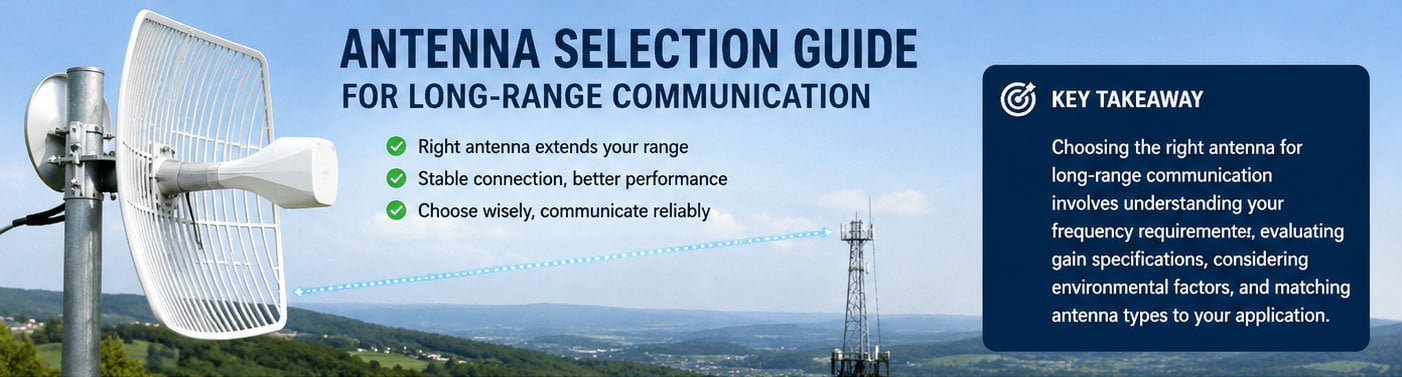
Choosing the right antenna for long-range communication involves understanding your frequency requirements, evaluating gain specifications, considering environmental factors, and matching antenna types to your application. The correct antenna can extend your communication range from hundreds of meters to several kilometers.
Let me share what I learned from helping hundreds of customers solve their long-range communication challenges. The principles I will explain here have proven effective across different industries and applications.
How to Select the Right Antenna for Long-Range Wireless Communication?
Many people think all antennas work the same way. They grab any antenna and expect good results. This approach rarely works for long-range applications. The physics of radio waves demand careful planning.
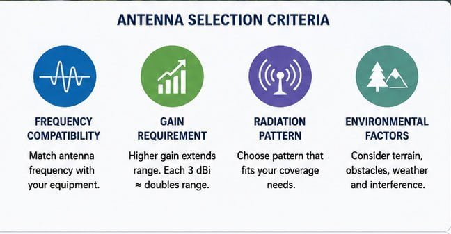
Select your antenna based on three core criteria: frequency compatibility with your equipment, sufficient gain for required distance, and appropriate radiation pattern for your coverage needs. Match these parameters to your specific environment and application requirements.
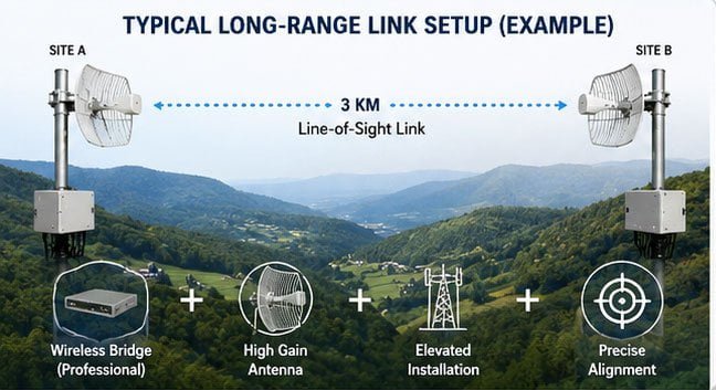
I worked with a TV station last year that needed real-time video transmission over 3 kilometers. They initially tried using TP-LINK 641G wireless routers with outdoor antennas. The connection kept dropping. Their broadcasts failed repeatedly.
The problem was clear. Consumer-grade routers lack professional bridge functionality. They cannot maintain stable connections over such distances. We recommended switching to dedicated wireless bridge equipment instead.
Here is what we implemented:
| Component | Specification | Purpose |
|---|---|---|
| Wireless Bridge | Professional grade | Point-to-point link establishment |
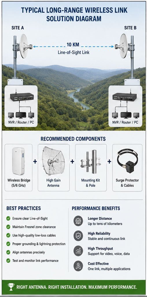
| Grid Parabolic Antenna | High gain directional | Focus energy in transmission direction |
| Installation Height | Elevated position | Clear line-of-sight path |
| Antenna Alignment | Precise pointing | Maximum signal strength |
The results exceeded expectations. The 3-kilometer link now transmits video streams reliably. The system handles live broadcasts, internet access, VoIP calls, and video surveillance. One investment serves multiple purposes.
Line-of-sight matters tremendously. Buildings, trees, and hills block radio signals. We ensured both ends could "see" each other directly. This simple requirement makes or breaks long-range links. Calculate your Fresnel zone clearance. Obstacles within this zone cause signal degradation even if line-of-sight exists.
Choosing the Best Antenna for Extended Communication Range?
Distance requirements drive antenna selection. A 500-meter link needs different solutions than a 10-kilometer connection. Power regulations also limit your options. You cannot simply increase transmit power indefinitely.
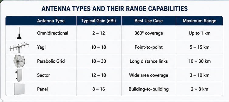
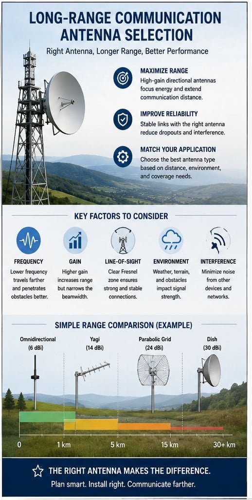
For extended range, prioritize high-gain directional antennas like Yagi, parabolic grid, or sector antennas. These designs concentrate radio energy in specific directions rather than radiating equally in all directions, effectively multiplying your transmission distance.
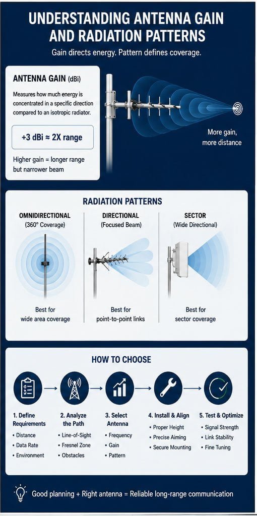
Think of antenna gain like a flashlight versus a floodlight. Omnidirectional antennas spread signals in all directions like floodlights. They illuminate everything nearby but lack distance. Directional antennas work like focused flashlight beams. They reach much farther in one direction.
Gain is measured in dBi (decibels relative to isotropic radiator). Each 3 dBi increase roughly doubles your effective range. However, higher gain narrows the beam width. You must aim more precisely.
Antenna Types and Their Range Capabilities
| Antenna Type | Typical Gain | Best Use Case | Maximum Range |
|---|---|---|---|
| Omnidirectional | 2-12 dBi | 360° coverage | Up to 1 km |
| Yagi | 10-18 dBi | Point-to-point | 5-15 km |
| Parabolic Grid | 18-30 dBi | Long distance links | 10-30 km |
| Sector | 12-18 dBi | Wide area coverage | 3-10 km |
| Panel | 8-16 dBi | Building-to-building | 2-8 km |
I learned this lesson the hard way. A customer wanted WiFi coverage across a valley. They bought 15 dBi omnidirectional antennas. The signals barely crossed 500 meters. We replaced them with 18 dBi Yagi antennas pointing across the valley. Coverage improved immediately.
Frequency also affects range. Lower frequencies travel farther and penetrate obstacles better. A 900 MHz signal reaches much farther than 5.8 GHz under identical conditions. However, lower frequencies offer less bandwidth. You must balance range against data speed requirements.
A Complete Guide to Antenna Selection for Long-Distance Communication?
Selecting antennas involves more than just picking high gain numbers. Environmental conditions dramatically affect performance. Weather, terrain, and interference sources all matter. I have seen perfect installations fail because of overlooked factors.
Successful long-distance antenna selection requires analyzing path loss, calculating link budget, choosing appropriate polarization, and accounting for weather effects. Document your requirements first, then match antenna specifications to these real-world conditions.
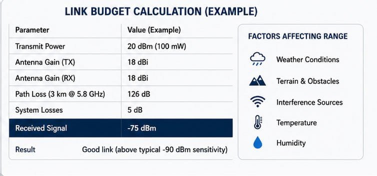
Start with a link budget calculation. This mathematical analysis predicts if your proposed system will work. The formula considers transmit power, cable losses, antenna gains, distance, and receiver sensitivity.
Basic link budget formula: Received Power = Transmit Power + Transmit Antenna Gain - Path Loss - Cable Losses + Receive Antenna Gain
Path loss increases with distance and frequency. Free space path loss follows this equation: FSPL (dB) = 20 log(d) + 20 log(f) + 32.45, where d is distance in kilometers and f is frequency in MHz.
Environmental Factors Affecting Antenna Performance
| Factor | Impact | Mitigation Strategy |
|---|---|---|
| Rain | Signal attenuation above 10 GHz | Use lower frequencies or increase power margin |
| Trees | Blockage and absorption | Raise antenna height or find clear path |
| Buildings | Reflection and multipath | Use directional antennas, adjust positioning |
| Temperature | Equipment performance variation | Use weatherproof enclosures |
| Wind | Physical movement affecting alignment | Secure mounting with proper hardware |
Polarization matching is crucial but often ignored. Your transmitting and receiving antennas must use the same polarization. Vertical polarization works best for mobile applications. Horizontal polarization performs better for fixed point-to-point links. Cross-polarization causes severe signal loss.
Cable quality matters as much as the antenna itself. Cheap cables introduce significant losses. At 2.4 GHz, RG58 cable loses about 1 dB per meter. LMR400 cable loses only 0.2 dB per meter. Over 10 meters, this difference equals 8 dB—more than doubling your antenna gain requirement.
How to Pick an Antenna for Maximum Signal Coverage?
Coverage patterns vary dramatically between antenna types. You must match the pattern to your specific needs. A point-to-point link needs narrow beams. Area coverage requires wider patterns. Mixing these up wastes resources.
For maximum coverage, select antenna beamwidth and mounting height based on your coverage area shape. Omnidirectional antennas suit circular areas, sector antennas cover wedge shapes, and directional antennas focus on specific zones or distant points.
Beamwidth specifications include two numbers: horizontal and vertical. A 30° horizontal by 15° vertical beamwidth creates an elongated pattern. Understanding these numbers helps predict actual coverage.
I helped a marina cover their dock area. The initial design used omnidirectional antennas mounted at ground level. Coverage was poor. We switched to sector antennas mounted 10 meters high. The elevated position combined with appropriate beamwidth provided complete coverage using fewer access points.
Coverage Calculation Guidelines
| Coverage Type | Recommended Antenna | Mounting Considerations | Expected Performance |
|---|---|---|---|
| Single building | Panel or sector (90-120°) | External wall mount | Good indoor penetration |
| Campus area | Multiple sectors (60-90°) | Central tower position | Overlapping coverage |
| Point-to-point | High gain directional | Line-of-sight elevation | Maximum distance |
| Road/linear | Directional or sector | Height above obstacles | Continuous coverage |
Height provides tremendous advantage. Doubling antenna height often increases coverage area by four times. However, local regulations may restrict tower heights. Always check zoning requirements before planning installations.
The first Fresnel zone must stay clear of obstacles. This elliptical area between antennas affects signal quality even when line-of-sight exists. Calculate the zone radius at the midpoint: r = 17.3 × √(d/4f), where r is radius in meters, d is total distance in kilometers, and f is frequency in GHz.
The Ultimate Guide to Long-Range Communication Antennas?
Long-range systems combine multiple components working together. The antenna is critical but not the only factor. Proper system design considers every element from radio to antenna tip. I have seen expensive antennas fail because of poor cable choices.
Build long-range systems by selecting frequency bands with favorable propagation, using high-quality low-loss cables, choosing weather-resistant connectors, and installing proper lightning protection. Each component affects overall performance and reliability.
Cable selection deserves careful attention. Use the shortest practical cable length. Choose high-quality coaxial cable rated for your frequency. LMR400 or LMR600 work well for most applications. Cheap cables destroy system performance.
Connector quality matters equally. Poor connectors introduce reflections and losses. Use compression connectors rather than crimp types. Weatherproof all outdoor connections with self-vulcanizing tape and heat shrink. Water intrusion causes mysterious intermittent failures.
Complete System Component Checklist
| Component | Selection Criteria | Common Issues | Best Practices |
|---|---|---|---|
| Radio equipment | Output power, receiver sensitivity | Insufficient power margin | Choose professional-grade equipment |
| Coaxial cable | Low loss at operating frequency | Using incorrect cable type | Calculate acceptable loss budget |
| Connectors | Match cable and equipment | Poor crimping technique | Use compression connectors |
| Lightning protection | Rated for frequency and power | Inadequate grounding | Install proper surge arrestors |
| Mounting hardware | Wind load rating | Insufficient strength | Use manufacturer-approved hardware |
Lightning protection is not optional for outdoor installations. Surge arrestors should be installed where cables enter buildings. Proper grounding prevents equipment damage and ensures safety. Ground resistance below 10 ohms provides effective protection.
I installed a 20-kilometer wireless link connecting two factory buildings. The customer questioned the expense of quality cables and lightning protection. Three months later, nearby lightning strikes destroyed unprotected equipment at another facility. Our protected system continued operating without issues. The customer understood the value.
Interference management becomes critical at longer ranges. Frequency scanning reveals crowded channels. Select the clearest frequency available. In congested environments, consider licensed frequency bands. The extra cost buys interference-free operation.
Key Factors to Consider When Choosing a Long-Range Antenna?
Technical specifications tell only part of the story. Real-world performance depends on correct interpretation of these numbers. Manufacturers measure specifications under ideal laboratory conditions. Your actual results will vary based on installation quality.
Consider VSWR under 1.5:1, appropriate frequency range covering your application, sufficient power handling for your transmitter, and mechanical durability for your environment. Also verify connector compatibility and check certification requirements for your region.
VSWR (Voltage Standing Wave Ratio) indicates how well the antenna matches your transmission line impedance. Poor matching reflects power back toward the transmitter instead of radiating. Values below 1.5:1 are acceptable. Values above 2:1 indicate problems. Measure VSWR across your operating frequency range.
I encountered a customer using beautiful-looking antennas with terrible VSWR. Specifications claimed 1.5:1 but actual measurements showed 2.5:1. The manufacturer measured at a single frequency. The customer operated across a wider band. Always verify specifications match your actual use case.
Critical Specification Checklist
| Specification | Why It Matters | Acceptable Range | Red Flags |
|---|---|---|---|
| VSWR | Efficiency of power transfer | < 1.5:1 preferred | > 2.0:1 across band |
| Gain | Effective transmission distance | Match link budget requirements | Unrealistic gain claims |
| Power handling | Transmitter compatibility | 2x your transmit power minimum | Underrated specifications |
| Wind survival | Physical durability | Local wind speed + margin | Missing specification |
| Temperature range | Operational reliability | Match climate extremes | Limited range |
Frequency range must cover your entire operating band. Some antennas specify center frequency gain but perform poorly at band edges. This matters for systems using frequency hopping or multiple channels. Verify performance across your complete frequency range.
Power handling capacity must exceed your transmitter output. Include safety margin for reflected power. If your transmitter outputs 1000 watts, choose antennas rated for at least 2000 watts. This prevents damage from temporary mismatches or reflections.
How to Improve Communication Distance with the Right Antenna?
Improving existing systems often proves more cost-effective than complete replacement. Small changes can dramatically increase range. I have helped customers double their effective range with simple antenna upgrades and adjustments.
Improve distance by upgrading to higher gain antennas, optimizing antenna height and alignment, reducing cable losses, eliminating interference sources, and adjusting transmit power within legal limits. Often, proper installation matters more than equipment specifications.
Start with alignment verification. Even professional installations drift over time. Wind, temperature changes, and settling affect antenna pointing. A few degrees misalignment at 10 kilometers means missing the target by hundreds of meters.
Use spectrum analyzers or signal strength meters for precise alignment. Point the antenna while monitoring received signal strength. The peak signal indicates optimal alignment. Document the final position for future reference. Seasonal foliage growth may require realignment.
Distance Improvement Strategies
| Strategy | Expected Improvement | Investment Level | Difficulty |
|---|---|---|---|
| Proper alignment | 3-6 dB gain | Minimal | Easy |
| Cable upgrade | 2-5 dB gain | Moderate | Medium |
| Antenna upgrade | 3-10 dB gain | Moderate to high | Medium |
| Height increase | 3-10 dB gain | High | Difficult |
| Interference reduction | Variable | Minimal to moderate | Easy to medium |
Remove obstacles in the Fresnel zone. Sometimes trimming trees or relocating antennas slightly improves performance dramatically. A few meters height increase can clear critical obstacles. Calculate Fresnel zone clearance and verify physical clearance.
Replace aging cables and connectors. Cable losses increase over time from moisture intrusion and corrosion. Connectors oxidize, increasing resistance. I have seen 10-year-old installations lose 6 dB from cable degradation alone. New cables restored full performance.
Consider antenna diversity for difficult paths. Using two receive antennas with automatic switching reduces fading effects. The small additional cost provides more reliable connections. This technique works especially well for mobile applications.
Long-Range Antenna Selection: Tips for Better Signal Performance?
Professional installations follow systematic approaches. Random trial-and-error wastes time and money. I learned these tips from thousands of installations across diverse environments. These practical guidelines prevent common mistakes.
Achieve better performance through site surveys, professional installation practices, regular maintenance schedules, and documentation of all settings. Use proper tools for installation and measurement rather than relying on guesswork.
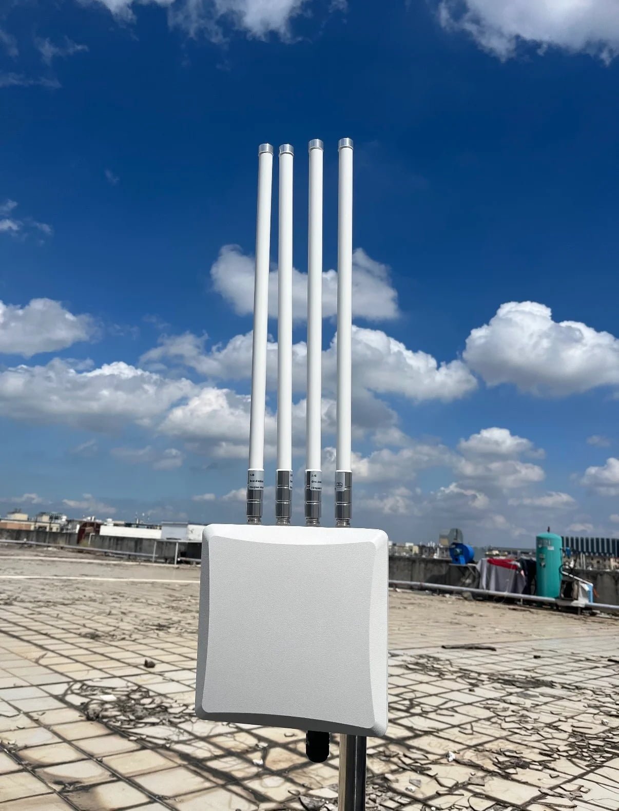
Site surveys identify potential problems before installation. Visit both ends of the link. Verify line-of-sight using GPS coordinates and mapping tools. Check for planned construction that might block your path. Identify local interference sources.
I learned this lesson after installing a link that worked perfectly for six months. Then new construction blocked our path. The customer blamed us for poor planning. Now I always verify development plans with local authorities before finalizing installations.
Professional Installation Best Practices
| Practice | Purpose | Tools Needed | Common Mistakes |
|---|---|---|---|
| Site survey | Path verification | GPS, maps, compass | Skipping this step |
| Cable testing | Loss verification | Cable tester, VSWR meter | Assuming cables are good |
| Alignment | Maximum signal | Signal meter, compass | Visual alignment only |
| Weatherproofing | Reliability | Tape, sealant, heat shrink | Inadequate protection |
| Documentation | Future maintenance | Camera, notebook | No records kept |
Use proper mounting hardware rated for local wind conditions. Under