
Choosing the right GNSS antenna for RTK positioning and high-precision applications can seem like a complex task, fraught with technical jargon and numerous specifications. If you're a system integrator, equipment manufacturer, or an engineer relying on centimeter-level accuracy, making an uninformed decision could lead to unreliable data, increased operational costs, and ultimately, project failures. I understand the pressure to get it right the first time.
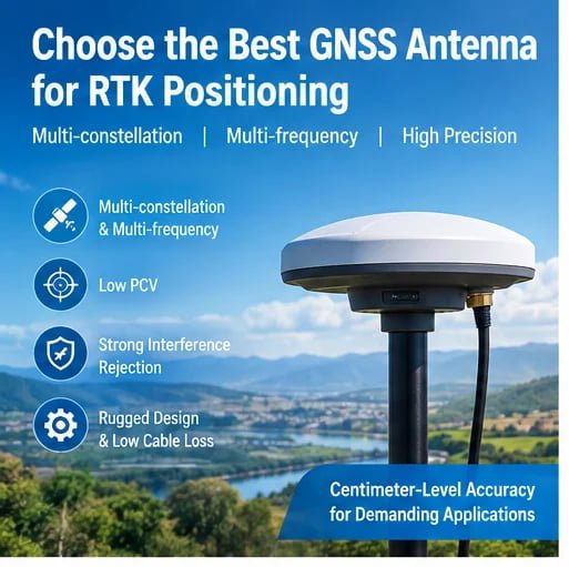
The optimal GNSS antenna for RTK positioning and high-precision applications is one that supports multi-constellation and multi-frequency signals, exhibits low Phase Center Variation (PCV), offers robust interference rejection, and is mechanically suitable for its operating environment with minimal cable loss. Prioritizing these features ensures the stability and precision critical for demanding RTK (Real-Time Kinematic) operations.
Now that you have the core answer, let's dive deeper into the specific factors and considerations that will help you select the ideal GNSS antenna for RTK positioning and high-precision applications, ensuring your systems perform at their peak.
How do Multi-Constellation and Multi-Frequency Capabilities Impact RTK Accuracy?
Are you struggling to achieve consistent centimeter-level accuracy in varied environments, especially when signal availability is challenging? Relying on a single GNSS constellation or frequency band can severely limit your RTK system's performance, leading to frustrating data gaps and reduced precision. The need for robust, continuous positioning demands a more advanced approach.
Multi-constellation and multi-frequency capabilities are fundamental for achieving superior RTK accuracy and reliability. By simultaneously tracking signals from multiple satellite systems (GPS, GLONASS, Galileo, BeiDou) across various frequency bands (L1, L2, L5, E5, B1, B2), a GNSS antenna provides more data, better satellite visibility, and improved resilience against atmospheric errors and signal blockages, directly enhancing RTK performance.

Dive Deeper: The Power of Redundancy and Resolution
In the realm of GNSS antenna for RTK positioning and high-precision applications, more data almost always translates to better accuracy and reliability. This is precisely where multi-constellation and multi-frequency antennas shine. As a manufacturer specializing in RF solutions, we've seen firsthand how crucial this is for our customers building cutting-edge RTK systems.
Understanding Multi-Constellation Support
Traditional GPS antennas primarily relied on the American Global Positioning System (GPS). However, the modern GNSS landscape includes several other robust satellite navigation systems:
- GLONASS (Russia): Offers a complementary set of satellites, improving coverage, especially at higher latitudes.
- Galileo (Europe): Provides highly accurate positioning, often with advanced signals.
- BeiDou (China): A rapidly expanding constellation, offering excellent coverage, particularly in the Asia-Pacific region and globally.
- QZSS (Japan), IRNSS (India): Regional systems that further augment global constellations.
When a GNSS antenna for RTK positioning can track signals from all or most of these constellations simultaneously, it gains significant advantages:
- Increased Satellite Availability: More satellites in view means a stronger geometric dilution of precision (GDOP), leading to higher positional accuracy. Even if some satellites are blocked by buildings or terrain, the system has a higher chance of maintaining a lock on enough others to continue RTK operations.
- Improved Redundancy: If one constellation experiences outages or signal degradation, the system can rely on others, ensuring continuity of service.
- Faster Fix Times: More available signals allow RTK algorithms to achieve a fixed solution more quickly, which is vital for dynamic applications.
The Role of Multi-Frequency Tracking
Beyond constellations, the ability to track multiple frequency bands emitted by satellites is equally critical for high-precision GNSS antennas. GNSS satellites transmit signals on several frequencies, commonly designated as L1, L2, L5 for GPS; E1, E5, E6 for Galileo; B1, B2, B3 for BeiDou; and G1, G2, G3 for GLONASS.
- Ionospheric Error Correction: The Earth's ionosphere causes signal delays that vary with frequency. By tracking signals on at least two frequencies (e.g., L1 and L2), RTK receivers can precisely calculate and mitigate these ionospheric delays, a major source of error in single-frequency systems. This is particularly important for longer baselines or during periods of high solar activity.
- Cycle Ambiguity Resolution: Multi-frequency data provides more robust observations, making it easier and faster for RTK algorithms to resolve carrier phase ambiguities—the cornerstone of centimeter-level accuracy. Faster ambiguity resolution means quicker time-to-first-fix (TTFF) and more stable solutions.
- Enhanced Robustness: Different frequencies have different propagation characteristics. Tracking multiple frequencies provides redundancy and resilience against interference, signal fading, and multipath effects, which is crucial for a stable GNSS antenna for RTK positioning.
For a manufacturer like us, designing a GNSS antenna that reliably captures these diverse signals requires meticulous engineering. It involves optimizing antenna elements, ensuring broad bandwidth coverage, and managing gain flatness across all required frequency bands. Our experience of over 17 years in RF solutions gives us the insight needed to develop antennas that meet these stringent multi-frequency demands. When evaluating suppliers, I always recommend verifying their testing capabilities to ensure real-world multi-frequency performance.
Why is Phase Center Variation (PCV) Critical for High-Precision GNSS Antennas?
Are your RTK measurements showing unexpected inconsistencies, even when your setup seems perfect and environmental conditions are ideal? You might be overlooking a critical, yet often subtle, factor that directly impacts centimeter-level accuracy: Phase Center Variation (PCV). Ignoring PCV can lead to systematic errors that undermine the reliability of your high-precision GNSS antenna system.
Phase Center Variation (PCV) is critical for high-precision GNSS antennas because it represents the spatial shift of the antenna's electrical center relative to its physical center as satellite signals arrive from different directions. For RTK systems demanding centimeter accuracy, a GNSS antenna with minimal and precisely calibrated PCV ensures that all measurements are referenced consistently, preventing systematic errors that would otherwise degrade positional precision.

Dive Deeper: The Invisible Anchor of Accuracy
The concept of the "phase center" is a cornerstone of precise GNSS measurements, especially when using a GNSS antenna for RTK positioning. While a GNSS antenna has a physical center, its electrical center—the point where the satellite signal's phase is effectively received—can shift depending on the direction from which the signal arrives. This phenomenon is known as Phase Center Variation (PCV).
What is Phase Center Variation (PCV)?
Imagine a tiny, perfect point within the antenna where all signals are received. In reality, due to the antenna's physical structure, impedance matching, and dielectric properties, this point isn't fixed. Instead, it moves slightly as the satellite signal's angle of arrival (elevation and azimuth) changes.
- Nominal Phase Center: This is the average or reference point for the electrical center, often close to the antenna's physical center.
- Phase Center Offset (PCO): The fixed vector displacement between the antenna's mechanical reference point (e.g., the bottom of the mount) and its nominal phase center.
- Phase Center Variation (PCV): The deviation of the actual phase center from its nominal position as a function of the signal's direction. It's typically expressed in millimeters and can be several millimeters to over a centimeter for lower-quality antennas.
Why is PCV Critical for RTK?
For high-precision GNSS antennas used in RTK, where accuracies of a few centimeters or even millimeters are targeted, PCV becomes a significant error source:
- Systematic Biases: If PCV is not accounted for, each satellite observation will be slightly misreferenced, leading to systematic biases in the calculated position. These errors are often consistent and can accumulate, making it difficult to achieve true centimeter-level accuracy.
- Baseline Dependence: The impact of PCV can be more pronounced on shorter baselines, where other errors (like atmospheric delays) are less dominant.
- Consistency Across Antennas: When using multiple antennas (e.g., a base station and a rover), differences in their PCV patterns can introduce errors if not properly calibrated.
Mitigating PCV: Manufacturer's Role
As an experienced manufacturer of GNSS antennas for RTK positioning, we understand that minimizing and characterizing PCV is paramount. This involves:
- Antenna Design: Utilizing specific antenna element geometries (e.g., choke rings, advanced patch designs, or helical structures) can intrinsically reduce PCV. My engineering team often spends significant time in simulation and physical prototyping to optimize these designs.
- Precise Manufacturing: Consistent manufacturing processes ensure that PCV characteristics are uniform across production batches.
- Calibration: High-end high-precision GNSS antennas are individually calibrated in specialized anechoic chambers. This process maps the antenna's PCV across its entire hemisphere of operation, creating a correction model that can be loaded into the RTK receiver. These calibration files (often in ANTEX format) are essential for achieving the highest accuracy. Buyers should always inquire about the availability of such calibration data.
- Frequency Dependence: PCV can also vary slightly across different frequency bands. Therefore, comprehensive calibration often includes PCV values for L1, L2, L5, and other supported frequencies.
| Feature | Low PCV Antenna (High-Precision) | High PCV Antenna (Standard) |
|---|---|---|
| Accuracy | Centimeter to millimeter level (after calibration) | Meter to decimeter level |
| Error Source | Minimal systematic bias due to antenna electrical center shifts | Significant systematic bias due to varying electrical center |
| Applications | RTK, Surveying, Autonomous Vehicles, Precision Agriculture | Standard navigation, asset tracking, general mapping |
| Cost | Higher (due to advanced design and calibration) | Lower |
| Design | Optimized elements, choke rings, precise manufacturing | Basic patch or ceramic designs |
| Calibration | Crucial, often individually calibrated and provided with data | Generally not calibrated for PCV |
When evaluating a GNSS antenna for RTK positioning, always ask about its PCV specifications and if calibration reports are available. A manufacturer's commitment to minimizing and characterizing PCV directly reflects their understanding of true high-precision performance.
How Can a GNSS Antenna Mitigate Multipath and Interference?
Have you experienced inexplicable drops in RTK solution quality or accuracy in urban canyons, near large structures, or when operating close to radio transmitters? These issues often stem from multipath and various forms of interference, which can severely compromise the performance of even the most sophisticated RTK receiver. Without effective mitigation at the antenna level, your high-precision GNSS antenna system remains vulnerable.
A well-designed GNSS antenna can significantly mitigate multipath and interference by employing features such as specialized antenna elements (e.g., choke rings), effective ground planes, robust filtering (e.g., SAW filters), and precise impedance matching. These design choices prevent unwanted reflected signals from reaching the receiver and block out-of-band noise, thereby preserving signal integrity and ensuring stable, accurate RTK positioning.

Dive Deeper: Protecting Signal Integrity at the Front End
For any GNSS antenna for RTK positioning and high-precision applications, maintaining signal integrity is paramount. Multipath and various forms of interference are insidious enemies that can corrupt even the strongest satellite signals before they ever reach the receiver's processing unit. My engineering team constantly innovates to build antennas that effectively combat these challenges.
Understanding Multipath
Multipath occurs when GNSS signals travel more than one path from the satellite to the receiver antenna. This happens when signals reflect off surfaces like buildings, the ground, or vehicles before reaching the antenna. The reflected signals are delayed and often phase-shifted relative to the direct line-of-sight signal.
- Impact on RTK: In an RTK system, multipath causes errors in carrier phase measurements, leading to incorrect ambiguity resolution and, consequently, degraded positioning accuracy or even a loss of fixed solution. It's particularly problematic in urban areas, under tree canopy, or near large metal objects.
Antenna-Based Multipath Mitigation:
- Antenna Element Design:
- Choke Ring Antennas: These are the gold standard for geodesy and high-accuracy applications. Choke rings act as electromagnetic traps, absorbing or scattering reflected signals arriving at low elevation angles, while allowing direct signals to pass.
- Ground Plane Optimization: A well-designed ground plane is essential. It prevents signals from below the antenna from reaching the element and can help suppress reflections from the immediate vicinity.
- Helical or Conical Elements: Some designs can inherently reduce sensitivity to low-angle multipath signals.
- Right-Hand Circular Polarization (RHCP): GNSS signals are transmitted with RHCP. An antenna designed to optimally receive RHCP signals will naturally attenuate left-hand circular polarized (LHCP) signals, which are often characteristic of reflections. The antenna's axial ratio (a measure of its ability to distinguish between RHCP and LHCP) is a key specification here. A lower axial ratio generally indicates better multipath rejection.
Understanding Interference
Interference refers to any unwanted electromagnetic signal that corrupts or masks the weak GNSS signals. This can come from various sources:
- Narrowband Interference: Specific frequencies from other communication systems (e.g., radio, Wi-Fi, cellular).
- Broadband Noise: General electromagnetic noise from electronic devices, motors, or poorly shielded equipment.
- Jamming: Intentional or unintentional high-power signals designed to overwhelm GNSS signals.
- Spoofing: Maliciously generated false GNSS signals designed to deceive a receiver about its true position.
Antenna-Based Interference Mitigation:
- Filtering:
- SAW Filters (Surface Acoustic Wave Filters): These are critical components placed immediately after the antenna element. They selectively pass only the GNSS frequency bands of interest while aggressively attenuating out-of-band noise and interference. A good SAW filter has steep skirts, meaning it transitions quickly from passband to stopband, and high out-of-band rejection.
- Low Noise Amplifier (LNA): While not strictly a filter, a high-quality LNA with a low noise figure (NF) and good linearity is essential. It amplifies the weak GNSS signals without introducing significant additional noise, ensuring that the signals are strong enough for the receiver to process.
- Shielding: Proper shielding within the antenna housing protects sensitive components from external electromagnetic interference.
- Impedance Matching: Precisely matching the impedance of the antenna element to the LNA and coaxial cable minimizes signal reflection within the antenna system itself, ensuring maximum signal transfer and reducing internal noise generation.
- Anti-Jamming/Anti-Spoofing Technologies: For the most critical applications, advanced antennas might incorporate controlled reception pattern antennas (CRPA) or digital beamforming techniques to nullify interference sources. While more complex and expensive, these are vital for military or highly sensitive infrastructure.
As a manufacturer with extensive experience in RF coaxial components, we integrate these features into our high-precision GNSS antennas. Our ISO9001 certification and rigorous testing protocols ensure that each antenna meets specified performance criteria for interference and multipath rejection. When selecting a supplier, look for transparent data on axial ratio, out-of-band rejection, and a commitment to quality manufacturing.
What Role Do Mechanical Design and Cable Selection Play in GNSS Antenna Performance?
Are you consistently achieving excellent performance from your GNSS antenna for RTK positioning in the lab, only to find it underperforms or fails in real-world field conditions? Often, the culprit isn't the antenna's electrical core, but rather overlooked aspects of its mechanical design and the associated cable selection. These seemingly mundane details can profoundly impact overall system reliability and accuracy.
The mechanical design of a GNSS antenna, including its housing, mounting options, and IP rating, ensures physical protection and stable positioning in harsh environments. Simultaneously, careful cable selection—considering type, length, and connector—is vital to minimize signal loss and maintain impedance matching. Neglecting either of these can introduce signal degradation, reduce overall gain, and compromise the long-term stability and accuracy of the high-precision GNSS antenna system.

Dive Deeper: Beyond the Electrical – Physical Integrity and Connectivity
When discussing a GNSS antenna for RTK positioning and high-precision applications, it's easy to get caught up in electrical specifications like frequency support and PCV. However, the antenna's physical embodiment and its connection to the receiver are equally critical. From our 17 years of manufacturing antennas in Shenzhen, we consistently advise customers on the importance of these practical considerations, especially for robust B2B applications.
Mechanical Design Considerations: Built for the Real World
The operating environment for an RTK system is rarely a pristine lab. Antennas often face extreme weather, vibrations, impacts, and exposure to various contaminants.
- Housing and Material:
- Durability: The housing material (e.g., UV-stabilized ABS, polycarbonate, anodized aluminum) must be robust enough to withstand its intended environment. Industrial, agricultural, or marine applications demand exceptionally strong housings.
- UV Resistance: For outdoor deployment, materials must resist degradation from prolonged sun exposure, preventing cracking and yellowing.
- Temperature Range: Ensure the antenna can operate reliably across the expected temperature extremes, from arctic cold to desert heat. Our product designs often specify wide operational temperature ranges to meet diverse global export markets.
- Ingress Protection (IP) Rating:
- This two-digit code (e.g., IP67, IP68) indicates the antenna's resistance to dust and water.
- First digit (solids): 6 is dust-tight.
- Second digit (liquids): 7 means protection against temporary immersion (up to 1m for 30min), 8 means protection against continuous immersion beyond 1m.
- For outdoor or harsh environments, an IP67 or IP68 rating is typically essential to prevent moisture ingress, which can cause signal degradation, corrosion, and internal damage.
- This two-digit code (e.g., IP67, IP68) indicates the antenna's resistance to dust and water.
- Mounting Options:
- Stability: The mounting mechanism must be rigid and secure to prevent antenna movement or vibration, which can introduce measurement errors.
- Standard Interfaces: Common mounting options include threaded poles (e.g., 5/8"-11), magnetic mounts, or screw-down flanges. Ensuring compatibility with your existing infrastructure is crucial.
- Ground Plane Integration: Some antennas require a specific ground plane size for optimal performance. Understanding whether the antenna is designed for integration with an external ground plane or if it includes one internally is important.
- Form Factor: From compact patch antennas for drones to robust survey-grade choke rings, the physical size and shape must fit the application's space constraints and aesthetic requirements. As an OEM/ODM specialist, we frequently work with customers to customize mounting structures and form factors.
Cable Selection: The Unsung Hero of Signal Integrity
The coaxial cable connecting the GNSS antenna for RTK positioning to the receiver is a critical, yet often underestimated, component. A poor cable choice can negate the benefits of even the best antenna.
- Cable Type and Loss:
- Attenuation: All cables introduce signal loss (attenuation), which increases with length and frequency. For GNSS signals, which are already very weak, minimizing loss is crucial.
- Common Cable Types:
- RG58/RG174: Thinner, flexible, but higher loss. Suitable for very short runs (e.g., <2 meters).
- LMR-200/LMR-240/LMR-400 (or equivalent): Thicker, lower loss, preferred for longer runs. LMR-400 offers significantly lower loss than LMR-200.
- HDF400/RG-223/RG-8: Other low-loss options available.
- Frequency Dependence: Loss increases significantly at higher frequencies (e.g., L5/E5 signals lose more power than L1/G1 over the same cable length).
- Consider this Table for Cable Attenuation (approximate values at 1.5 GHz per 100 ft/30m):
| Cable Type | Attenuation (dB/30m) | Diameter (mm) | Flexibility | Typical Use Cases |
|---|---|---|---|---|
| RG-174 | ~30 | 2.8 | High | Very short internal connections |
| RG-58 | ~15-20 | 4.9 | Medium | Short runs (up to 5m) |
| LMR-200 | ~10-12 | 4.9 | Medium | Moderate runs (5-10m) |
| LMR-400 | ~5-7 | 10.3 | Low | Longer runs (>10m), high-performance systems |
- Cable Length: Use the shortest possible cable length while still accommodating the installation. Every meter adds attenuation. For longer runs, a low-loss cable is mandatory, and sometimes an inline LNA (Low Noise Amplifier) booster is considered, though this can introduce its own noise.
- Connector Type:
- Standardization: SMA, TNC, N-type are common. Ensure compatibility with both the antenna and receiver.
- Quality: High-quality connectors with proper termination are crucial to prevent signal leakage, impedance mismatches, and physical failure. Poorly crimped connectors are a common source of signal issues. Our production line has strict QC for RF connector assembly.
- Impedance Matching: The antenna, cable, and receiver input should all be impedance-matched (typically 50 ohms). Mismatches cause reflections and signal loss.
- Environmental Durability: Cables should be rated for outdoor use if applicable (UV resistant, waterproof jacket).
For our target customers—communication equipment manufacturers and system integrators—these details are paramount. We offer a comprehensive range of RF coaxial cable assemblies and can customize lengths, connectors, and cable types to ensure optimal system performance and flexibility, even for small batch testing orders. This attention to detail extends beyond just the antenna to the entire RF signal path.
Frequently Asked Questions
What is RTK positioning?
RTK (Real-Time Kinematic) positioning is a satellite navigation technique used to enhance the precision of position data derived from satellite-based positioning systems. It achieves centimeter-level accuracy by using a base station at a known location to transmit real-time carrier phase measurements to a rover receiver, correcting for atmospheric and orbital errors.
What is the difference between single-band and multi-band GNSS antennas?
A single-band GNSS antenna receives signals on only one frequency (e.g., L1), making it susceptible to ionospheric errors and limiting accuracy. A multi-band GNSS antenna for RTK positioning receives signals on multiple frequencies (e.g., L1, L2, L5), allowing the receiver to precisely calculate and remove ionospheric delays, significantly improving accuracy and reliability for RTK and high-precision applications.
Can I use a standard GPS antenna for RTK?
While some standard GPS antennas may receive L1 signals, they are generally not suitable for RTK positioning. Standard antennas often lack multi-frequency and multi-constellation support, have higher Phase Center Variation (PCV), and offer insufficient interference and multipath rejection, which are all critical for achieving the centimeter-level accuracy required by RTK systems.
How important is the antenna's gain?
The antenna's gain is important as it indicates its ability to capture weak satellite signals. However, for a GNSS antenna for RTK positioning, too much gain can amplify noise along with the signal. The ideal is a balanced gain with a low noise figure, ensuring sufficient signal strength without overwhelming the receiver or increasing susceptibility to interference.
What does IP rating mean for a GNSS antenna?
The IP (Ingress Protection) rating for a high-precision GNSS antenna specifies its resistance to dust and water. An IP67 or IP68 rating, for example, indicates that the antenna is dust-tight and can withstand temporary or continuous immersion in water, respectively. This is crucial for ensuring the antenna's durability and reliability in outdoor or harsh operating environments.
Conclusion
Choosing the right GNSS antenna for RTK positioning and high-precision applications is not a decision to be taken lightly. As we've explored, achieving robust centimeter-level accuracy hinges on a careful evaluation of multi-constellation and multi-frequency capabilities, minimal Phase Center Variation, effective multipath and interference mitigation, and appropriate mechanical design and cable selection. These factors collectively ensure your RTK system performs reliably, consistently, and accurately in the most demanding environments. I believe that an informed choice in your antenna selection is a direct investment in the success and precision of your projects.
As a manufacturer with over 17 years of experience in communication antennas and RF solutions, we understand the specific needs of communication equipment manufacturers, system integrators, and those requiring precise positioning. We offer a range of customizable GNSS antennas and RF cable assemblies, designed to meet the rigorous demands of RTK and high-precision applications, with flexible MOQ and fast delivery. If you're seeking a reliable, high-performance GNSS antenna for RTK positioning that can be tailored to your exact specifications, I encourage you to reach out. Let's discuss how our expertise can help you achieve your precision goals.